The main dimensions of the worm wheel rim (diameters , , , , rim width) are determined during the design.
The radius of the recessed surface of the tops of the wheel teeth (Fig. 10) is determined by the diameter of the worm:
![]() ,
,
Where - pitch diameter worm
m– transmission module.
At the ends of the worm wheel, chamfers are made, rounded to standard value(the standard size range of chamfers is given in Table 8).
Worm wheels are not large diameter(up to 100-120 mm) perform whole. The thickness of the rim in this case can be taken:
![]() .
.
The dimensions of the disk and hub are the same as for prefabricated wheels.
Larger wheels are made teams to save expensive bronzes. Wheel disc made from cheaper cast iron or steel, ring gear- made of bronze.
The cutting of the worm wheel teeth is carried out after assembly.
Disk design depends on the volume of output. In small-scale production, disc blanks are obtained from rolled products or forgings, followed by turning (Fig. 11 A). In mass production (annual production volume over 100 pcs.), it is preferable to produce stamped or alloy wheels(Fig. 11 b).
To facilitate the removal of the workpiece from a stamp or mold, it is necessary to provide slopes and radii of curvature mm on the rim and hub. For forged and turned disks, the radii of curvature are mm.
Worm ring thickness S: ![]() .
.
Rim thickness: .
From here outside diameter disk: ![]() .
.
Rim inner diameter: ![]() .
.
Disk thickness, but not less.
Hub outer diameter:
![]() – for a steel hub with a keyed connection and an interference fit;
– for a steel hub with a keyed connection and an interference fit;
![]() – for a steel hub with a spline connection;
– for a steel hub with a spline connection;
![]() – for a cast iron hub.
– for a cast iron hub.
Note: The shaft diameter is determined after calculating the shafts.
Hub length:
– smaller values for an interference fit on the shaft, larger values for a transitional fit;
It is finally accepted after calculating the shaft-hub connection.
Geared worm wheels most often have a symmetrically located hub.
Worm wheels weighing more than 20 kg must have 4...6 holes on the disk to ensure slinging. The diameter of the holes is taken structurally.
Sharp edges at the ends of the hub are blunted with chamfers, the dimensions of which are taken according to Table 8.
The same chamfer size can be used to blunt the inner edge of the rim.
Connection of the crown with the disk must ensure the transmission of high torque and relatively small axial force. The design of the crown and the method of connection to the disk depends on the output volume.
At single and small-scale production And Not large sizes wheels(300 mm) the crowns are placed on the disk with interference (Fig. 12).
Rim thickness: ![]() .
.
With a constant direction of rotation of the worm wheel, a shoulder is provided on the outer surface of the disk (Fig. 11 A), which absorbs the axial force. The dimensions of the collar can be taken as follows: ; . The reverse gear wheel can be made without a shoulder.
For relatively small interference (or acceptance of interference without calculation), to guarantee non-rotation, screws are installed at the junction of the worm ring and the disk (Fig. 12 b) as a cylindrical key (usually 3...4 pieces around the circumference).
At large wheel sizes(300 mm) the crown can be attached to the disk using tight-fitting bolts (for reaming) (Fig. 13) or rivets. In this case, the crown is pre-centered along the diameter D, pairing is performed using a transitional fit.
Rim thickness: ![]() .
.
In this design, it is necessary to provide reliable locking of the nut from self-unscrewing, To do this, use spring washers Not recommended .
At mass production It is more economically profitable to produce wheels with rims obtained by casting. A cast iron or steel disk heated to 700…800ºС is placed in a metal mold, heated to 150…200ºС and filled with molten bronze. When cooling, a tension occurs between the disk and the crown, caused by the shrinkage of the solidifying liquid metal of the crown.
The thickness of the crown during casting is assumed to be .
Discs are made by turning, stamping or die casting. The outer surfaces of cast disks are not mechanically processed. They are degreased and cleaned of oxide films using chemical treatment. 6...8 recesses are provided on the rim of the disk; after casting, protrusions are formed on the rim that absorb both circumferential and axial forces.
The concave outer surface of the disk (Fig. 14 A,b) are obtained by turning. Transverse grooves are obtained by radial feed of a cutter: disk (Fig. 14 A) - perpendicular to the axis of rotation of the wheel or cylindrical (Fig. 14 b) – parallel to the axis of rotation. Slot dimensions: ![]() ;
; ![]() .
.
The recesses on the disk rim can be drilled (Fig. 14 V).
In Fig. 14 G,d shows discs with grooves obtained by casting into a disc in a mold.
The diameter of the circle of the projections and the width of the ring gear are determined during the design calculation.
Rim thickness S for all types of wheels you can accept:
At the ends of the ring gear (teeth and rim corners), chamfers are made (Fig. 2.3):
![]() ,
,
which are rounded to a standard value according to the same series as (see Table 2.3).
On all straight teeth gear wheels ah chamfer is performed at an angle of 45° (Fig. 2.3 A). On helical and chevron wheels with a hardness of less than 350 HB, the chamfer is made at an angle of 45° (Fig. 2.3 A), at higher hardness - at an angle of 15...20° (Fig. 2.3 b).
 |
|||
| A | b | ||
| Rice. 2.3. Chamfer design at the ends of the ring gear |
Hub outer diameter (see Fig. 2.2):
![]()
![]()
![]() – for a cast iron hub.
– for a cast iron hub.
Hub length:
– optimal value;
Gear wheels for gearboxes most often have a symmetrically located hub.
Sharp edges at the ends of the hub are blunted with chamfers, the dimensions of which are taken according to table 2.5.
| 20…30 | 30…40 | 40…50 | 50…80 | 80…120 | 120…150 | 150…250 | 250…500 | |
| 1,0 | 1,2 | 1,6 | 2,0 | 2,5 | 3,0 | 4,0 | 5,0 |
Small diameter gears(up to 150 mm) have a simple shape. The workpiece is obtained from rolled stock (Fig. 2.4 A and rice 2.5 A) or free forging (Fig. 2.4 b and rice 2.5 b). They are used in both serial and single production.
This design can be used if the thickness of the rim in the weakened area keyway, will be at least 2.5 m, otherwise the gear wheel must be made integral with the shaft (see paragraph 2.4.6.2, “Design of gear shaft”).
To reduce the amount of precision cutting, grooves are made on the wheel rims (for wheels > 80 mm) (Fig. 2.5). The same wheel design can be used for wheels of larger diameter (up to 500 mm) in single production, if there are no strict weight requirements.
Forged wheels(Fig. 2.6) - wheels of larger diameter (up to 500 mm) in single and small-scale production are produced from rolled stock by open forging followed by turning.
Disc thickness. To reduce weight, in technically justified cases, you can take 4...6 large-diameter holes in the disk.
Curvature radii.
Stamped wheels– in mass production, wheel blanks with a diameter of up to 500 mm are obtained from round steel by forging in dies. With an annual production volume of up to 100 pcs. Forging in the simplest one-sided backing dies is economically justified (Fig. 2.7). For free removal of workpieces from the stamp, the values of stamping slopes and radii of curvature are taken R³ 6 mm.
Disc thickness.
With an annual production volume of more than 100 pcs. double-sided stamps are used (Fig. 2.8).
To reduce the effect of volumetric heat treatment on accuracy geometric shape gear wheels can be made massive (Fig. 2.9): ![]() .
.
Solid wheels– used in mass production, as the least labor-intensive, for the manufacture of wheels with a diameter of over 500 mm. In terms of their load-bearing capacity, they are inferior to wheels with a forged or rolled rim. Up to a diameter of 900 mm, they are mainly made with single disks (Fig. 2.10 A), and when large diameters and width - reinforced by ribs (Fig. 2.10 b) or are made with double disks (Fig. 2.10 V).
The spokes can have a cross-shaped, T-shaped, I-beam, oval or other cross-sectional shape. The cross-sectional dimensions of the spokes at the hub are determined from their conditional calculation for bending. Since the rim stiffness is low, the load distribution between the spokes is very uneven. If the circumferential force on the wheel is , then it is conventionally assumed that the load on the most loaded spoke is:
 ,
,
Where T– torque on the wheel;
d– pitch diameter of the wheel;
– number of spokes.
Then the condition for the strength of the spokes is:

where is the axial moment of resistance of the spoke section.
For free removal of blanks from the mold, the values of casting slopes and radii of curvature are taken R³ 10 mm.
To avoid runout and vibration during operation, gears are balanced by drilling holes at the end of the rim if their rotation speed exceeds 1000 rpm.
2.4.6.2 Gear shaft design
Gear shafts are used in cases where the diameter of the shaft is close in size to the diameter of the gear (mainly in gearboxes at 3.15),
The design of the gear shaft must ensure cutting of teeth with free exit of the tool (Fig. 2.11 A). For large gear ratios, it is permissible to manufacture a gear shaft with teeth cutting into the shaft body (Fig. 2.11 b,V). The output of the cutter is determined graphically by its outer diameter. It is advisable to avoid the use of mortise gear shafts, since in this case milling and grinding of teeth is difficult. In this case, the diameter of the circle of the gear cavities should not be less than the calculated diameter of the shaft.
If possible, the tool entry should be provided from the shaft shoulder (Fig. 2.11 G).
2.4.6.3 Worm design
The worms work together with the shaft. Mounted worms are used extremely rarely. The main dimensions of the worm (diameters , , , length) are determined during design. Approximate distance between supports l determined at the stage of preliminary design of the gearbox.
One of the main requirements for the design of a worm shaft is to ensure high rigidity. For this purpose, they try to keep the distance between the supports as small as possible.
The diameter of the worm shaft in the unthreaded part is chosen to ensure, if possible, free exit of the tool when processing turns and the required size of the thrust shoulder for the bearing (Fig. 2.12 A).
If the diameter of the worm is not large enough to provide the required shoulder height, then it is necessary to provide a shoulder (Fig. 2.12 b).
With a small diameter, the worm must be made according to Fig. 2.12 V. In this case, the shoulders are made as shown in Fig. 2.12 A, and according to Fig. 2.12 b.
2.4.6.4 Worm wheel design
The main dimensions of the worm wheel rim (diameters , , , , rim width) are determined during the design.
The radius of the recessed surface of the tops of the wheel teeth (Fig. 2.13) is determined by the diameter of the worm:
![]() ,
,
where is the pitch diameter of the worm.
m– transmission module.
At the ends of the worm wheel, chamfers are made, rounded to a standard value (the standard size range of chamfers is given in Table 2.6).
Worm wheels of small diameter (up to 100-120 mm) perform whole. The thickness of the rim in this case can be taken:
![]() .
.
The dimensions of the disk and hub are the same as for prefabricated wheels.
Larger wheels are made teams to save expensive bronzes. Wheel disc made from cheaper cast iron or steel, ring gear- made of bronze.
The cutting of the worm wheel teeth is carried out after assembly.
Disk design depends on the volume of output. In small-scale production, disc blanks are obtained from rolled products or forgings, followed by turning (Fig. 2.14 A). In mass production (annual production volume over 100 pcs.), it is preferable to manufacture stamped or cast disks (Fig. 2.14 b).
To facilitate the removal of the workpiece from a stamp or mold, it is necessary to provide slopes and radii of curvature mm on the rim and hub. For forged and turned disks, the radii of curvature are mm.
Worm ring thickness S: ![]() .
.
Rim thickness: .
Hence the outer diameter of the disk: ![]() .
.
Rim inner diameter: ![]() .
.
Disk thickness, but not less.
Hub outer diameter:
![]() – for a steel hub with a keyed connection and an interference fit;
– for a steel hub with a keyed connection and an interference fit;
![]() – for a steel hub with a spline connection;
– for a steel hub with a spline connection;
![]() – for a cast iron hub.
– for a cast iron hub.
Hub length:
– smaller values for an interference fit on the shaft, larger values for a transitional fit;
– optimal value;
It is finally accepted after calculating the shaft-hub connection.
Geared worm wheels most often have a symmetrically located hub.
Worm wheels weighing more than 20 kg must have 4...6 holes on the disk for slinging. The diameter of the holes is taken structurally.
Sharp edges at the ends of the hub are blunted with chamfers, the dimensions of which are taken according to table 2.6.
| 20…30 | 30…40 | 40…50 | 50…80 | 80…120 | 120…150 | 150…250 | 250…500 | |
| 1,0 | 1,2 | 1,6 | 2,0 | 2,5 | 3,0 | 4,0 | 5,0 |
The same chamfer size can be used to blunt the inner edge of the rim.
Connection of the crown with the disk must ensure the transmission of high torque and relatively small axial force. The design of the crown and the method of connection to the disk depends on the output volume.
At single and small-scale production And small sizes wheels(300 mm) the crowns are placed on the disk with interference (Fig. 2.15).
Rim thickness: ![]() .
.
With a constant direction of rotation of the worm wheel, a shoulder is provided on the outer surface of the disk (Fig. 2.15 A), which absorbs the axial force. The dimensions of the collar can be taken as follows: ; . The reverse gear wheel can be made without a shoulder.
For relatively small interference (or acceptance of interference without calculation), to guarantee non-rotation, screws are installed at the junction of the worm ring and the disk (Fig. 2.15 b) as a cylindrical key (usually 3...4 pieces around the circumference).
At large wheel sizes(300 mm) the crown can be attached to the disk using tight-fitting bolts (for reaming) (Fig. 2.16) or rivets. In this case, the crown is pre-centered along the diameter D, pairing is performed using a transitional fit.
Rim thickness: ![]() .
.
In this design, it is necessary to provide reliable locking of the nut from self-unscrewing, To do this, use spring washers Not recommended .
At mass production It is more economically profitable to produce wheels with rims obtained by casting. A cast iron or steel disk heated to 700…800ºС is placed in a metal mold, heated to 150…200ºС and filled with molten bronze. When cooling, a tension occurs between the disk and the crown, caused by the shrinkage of the solidifying liquid metal of the crown.
The thickness of the crown during casting is assumed to be .
Discs are made by turning, stamping or die casting. The outer surfaces of cast disks are not mechanically processed. They are degreased and cleaned of oxide films using chemical treatment. 6...8 recesses are provided on the rim of the disk; after casting, protrusions are formed on the rim that absorb both circumferential and axial forces.
The concave outer surface of the disk (Fig. 2.17 A,b) are obtained by turning. Transverse grooves are obtained by radial feed of a cutter: disk (Fig. 2.17 A) – perpendicular to the axis of rotation of the wheel or cylindrical (Fig. 2.17 b) – parallel to the axis of rotation. Slot dimensions: ; ![]() .
.
The recesses on the disk rim can be drilled (Fig. 2.17 V).
In Fig. 2.17 G,d shows discs with grooves obtained by casting into a disc in a mold.
2.4.6.5 Selection of fits, maximum deviations, tolerances of shapes and arrangement of surfaces, roughness.
Tolerances and maximum deviations of the dimensions of wheels and worms
Tolerances on the size of the diameter of the circle of the protrusions can be accepted: for gear wheels of the 7th degree of accuracy - h8, 8 degrees of accuracy – h9, 9 degrees of accuracy – h10. For 11th degree of accuracy (straight and narrow helical gear wheels in manual drives) in reverse gears – h11, in irreversible gears – h12.
Tolerance for hub length is accepted h11-h12.
Tolerances for other sizes are usually taken according to quality 14.
Roughness of wheel and worm surfaces
The surfaces of gear and worm gear elements must have the roughness indicated in Table 2.7.
Table 2.7
Roughness of the surfaces of gear and worm wheel elements
| Gear elements | Roughness, Ra, µm |
| Working surfaces of gear teeth | 0,8 – 0,1 |
| Working surfaces of worm wheel teeth | 0,8 – 0,4 |
| Working surfaces of worm turns | 0,4 – 0,2 |
| Tooth lug surfaces | 6,3 |
| Chamfers and grooves on gears and worm wheels | 6,3 |
| The ends of the hubs, based on the end of the shaft shoulders, at the ratio | 1,6 |
| The same with respect | 3,2 |
| Working surfaces of keyways | 1,6 |
| Non-working surfaces of keyways | 3,2 |
| Landing surfaces of holes during landing H7: | |
| for diameters ≤ 50 mm | 0,8 |
| for diameters > 50 mm | 1,6 |
Shaft design
2.4.7.1 Sketching shafts
The development of the shaft sketch can be started from the end of the shaft. It is recommended to use standard ends (Table 4, Appendix 5): cylindrical - in accordance with GOST 12080-66 or conical - in accordance with GOST 12081-72. Cylindrical shaft ends are easier to manufacture, but require additional axial fixation of the mounted parts. Tapered shaft ends are more difficult to manufacture, but provide simple and tight fit details. They are recommended for shafts with high speed rotation.
Recommended dimensions of chamfers and fillet radii are given in Table 2.8. If a section of the shaft needs to be ground during manufacturing, instead of the usual transition, a groove is provided for exit grinding wheel(Fig. 2.19, Table 2.9).
Shoulder height t taken constructively, depending on the nature of the load acting on the mounted part: from 1.25 r– for parts not experiencing axial loads, up to (2.0…2.5) r– for parts that bear strong axial loads. The diameters of the remaining sections of the shaft are determined sequentially, taking into account the height of the shoulders of each step.
Table 2.8
Shaft shoulder dimensions, mm
Table 2.9
Dimensions of the groove for the exit of the grinding wheel, mm
If a section of the shaft is intended for fitting a part, then it is necessary to provide a chamfer at the beginning of the section: at an angle of 45º - when landing with a gap or transitional fit; at an angle of 30º - when landing with an interference fit.
The lengths of the shaft sections are determined by drawing, taking into account the dimensions of the mounted parts, their relative position, the size of the required gaps between them, etc.
2.4.7.2 Fitting gears and worm wheels on shafts
The transmission of torque from the shaft to the wheel or vice versa, regardless of the type of fit, is carried out using keyed or splined connections.
In serial gearboxes general purpose Usually one of the transitional landings is used: H7/k6(tense), H7/m6(tight). These fits are used in mechanisms operating under light loads and subject to frequent disassembly. Transitional fits require additional fastening of the wheels against axial movement (spring rings, set screws, spacers, nuts, etc.).
In case of rare disassemblies, landings are used: H7/n6(deaf), H7/p6(light press). These landings also require additional securing of the wheels against axial movement.
The fit of gears on shafts in heavily loaded transmissions operating under vibration and shock loads is carried out using one of the press fits: H7/r6,H7/s6. The use of these landings, along with increasing the reliability of the connection, protects the wheels from axial movement.
2.4.7.3 Roughness of shaft surfaces
The surfaces of the shafts must have the roughness indicated in Table 2.10.
Table 2.10
Roughness of shaft surfaces
| Shaft elements | Roughness, Ra, µm |
| Fixed joints with sliding fit | 0,2 – 0,05 |
| Connections with transitional landings | 0,4 – 0,1 |
| Press and cone connections | 0,4 – 0,05 |
| Thrust collars of fixed cylindrical joints (working surfaces) | 1,6 – 0,4 |
| Fittings of rolling bearings on the shaft with bearing accuracy class: | |
| normal | 0,4 – 0,1 |
| elevated | 0,1 – 0,05 |
| Spline connections, centering: | |
| by outer diameter | 0,4 – 0,1 |
| by inner diameter | 0,8 – 0,2 |
| Key-groove connections (working edges of grooves) | 3,2 – 0,8 |
| External threads | 3,2 – 1,6 |
| Internal threads | 6,4 – 3,2 |
| Cylindrical contact seals with soft cuff elements (working surfaces of shafts) | 0,1 – 0,05 |
| Free surfaces of parts (ends and non-load-bearing cylindrical surfaces of shafts, chamfers, etc.): | |
| lightly loaded | 6,4 – 1,6 |
| loaded with high cyclic loads | 1,6 – 0,2 |
| Fillet: | |
| irresponsible purpose | 3,2 – 1,6 |
| parts loaded with high cyclic loads | 0,4 – 0,1 |
Worms for power transmissions are made of carbon or alloy steels with appropriate heat treatment, ensuring high hardness of the working surfaces. Worms of steel 15Х, 20Х, 12ХН2, 18ХГТ, 20ХФ etc. are subjected to carburization and hardening to hardness HRC58...63, and from steel St6, 40, 45, 40Х, 40ХН hardened to HRC45...55. Worms made from improved and normalized steels are used in low-speed and lightly loaded gears, as well as in the absence of equipment for grinding them. In gears with large-diameter wheels, the worm is made of bronze, and the wheel is made of cast iron (to save bronze). In most cases, the worm is made as a whole with a shaft, less often mounted, that is, made separately from the shaft and then attached to it.
The choice of worm wheel material mainly depends on the speed of sliding of the worm threads along the teeth of the wheel
Where v 1- peripheral speed of the worm; γ - pitch angle of the worm thread. Due to the tendency worm gear To prevent jamming and unfavorable conditions for its lubrication, the rims of the worm wheels are made of bronze. Less often they are made of cast iron and plastics. To save bronze, only a gear rim (rim with teeth) is made from it, and the center of the wheel, i.e., that part of it that is inside the rim, is made of cast iron or carbon steel. At sliding speeds v sk =5...30 m/s And long work without interruption, the rims of worm wheels are made of bronze BrOF10-1, BRONF with high antifriction and extreme pressure properties. At v sk ≤6 m/s gear rims are made from less expensive tin-free bronze BrAZH9-4L, BrAZHN10-4-4L and so on.; in this case, the worm must have hardness HRC≥45.
In a worm wheel of small diameter that is not subject to strong heating, the bronze rim is usually pressed onto the center and secured with screws to secure the connection. In wheels of large and medium diameters, the bronze rim is fastened to the center with screws. In mass production, worm wheels are made bimetallic, i.e., the bronze rim is cast centrifugally in a mold in which a cast iron center is placed. At sliding speeds v sk ≤2 m/s To reduce cost, worm wheels can be made entirely of cast iron SCh15, SCh18 And SCH20. To absorb shock during worm gear operation, dampen mechanical vibration, and minimize wear on the teeth of worm wheels, they are sometimes made of plastic. Plastic worm wheels are used in small power transmissions and devices; The materials for them are wood-laminated plastics (chipboard), textolite and polyamides (nylon and nylon). Shown is a plastic worm wheel made of textolite or wood-plastic plates mounted on a metal sleeve and bolted between steel disks. Otherwise, the design of a worm wheel is the same as a cogwheel.
Of the 12 degrees of accuracy in the manufacture of worm gears, regulated by GOST 13675-68 (ST SEV 311-76), 5, 6, 7, 8 and 9 degrees of accuracy are provided for power transmissions. In general mechanical engineering, 7, 8 and 9 degrees of accuracy are most often used. Selecting the degree of accuracy of the worm gear depending on the peripheral speed of the wheel v 2, worm and wheel processing and transmission applications can be done according to the table.
43. Kinematics of a worm gear. Worm gear efficiency. For each revolution of the worm, the cross-section of its turn shifts in the axial direction by the amount of thread stroke: t = p 1 z 1 , with speed u 1 = p 1 z 1 n 1. The worm wheel has a peripheral speed u 2 = pd 2 n 2 = pmz 2 n 2. Because u 1 = u 2, That z 1 n 1 = z 2 n 2 or z 1 w 1 = z 2 w 2. Therefore, the gear ratio
u = w 1/w 2= n 1/n 2 = z 2/z 1.
When moving, the turns of the worm slide along the teeth of the wheel as in screw pair. Sliding speed u S(Fig. 3.38, A) is directed tangentially to the helix of the worm. As a relative speed, it is equal to the geometric difference between the absolute speeds of the worm and the wheel:
/ cos g.
In Fig. Figure 3.38 shows the contact lines lying on the side surface of the cylindrical teeth ( b) and globoid ( V) gears, and also depicts the projections u of the sliding speed vectors, which in magnitude and direction are close to the peripheral speed of the worm.
If the angle of inclination contact lines to the sliding velocity vector is small, then the conditions for hydrodynamic lubrication are unfavorable. If the sliding speed is directed across the contact line, then conditions are created for the formation of an oil wedge that has a significant lifting force, and a fluid friction regime arises. Therefore, the load capacity of globoid gears is approximately 1,5 times higher than cylindrical.
The worms work together with the shaft. Mounted worms are used extremely rarely. The main dimensions of the worm (diameters,  ,
, , length
  ) are determined during design. Approximate distance between supports l determined at the stage of preliminary design of the gearbox.
One of the main requirements for the design of a worm shaft is to ensure high rigidity. For this purpose, they try to make the distance between the supports as small as possible.
|
|
|
|
|
|
|
Rice. 9. Design of cylindrical worms |


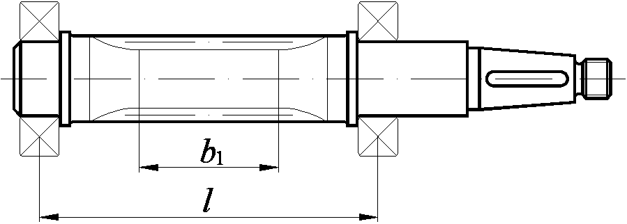
The diameter of the worm shaft in the unthreaded part is chosen to ensure, if possible, free exit of the tool when processing turns and the required size of the thrust shoulder for the bearing (Fig. 9 A).
If the diameter of the worm is not large enough to provide the required shoulder height, then it is necessary to provide a shoulder (Fig. 9 b).
With a small diameter, the worm must be made according to Fig. 9 V. In this case, the shoulders are made as shown in Fig. 9 A, and according to Fig. 9 b.
4.2 Worm wheel design
The main dimensions of the worm wheel rim (diameters  ,
, ,
, ,
, , crown width
  ) are determined during design.
Radius of the notch surface of the wheel tooth tips  (Fig. 10) is determined by the diameter of the worm:
 ,
,
Where  – pitch diameter of the worm.
m– transmission module.
Chamfers are made at the ends of the worm wheel  with rounding to the standard value (the standard size range of chamfers is given in Table 8).
Worm wheels of small diameter (up to 100-120 mm) perform whole. The thickness of the rim in this case can be taken:
 .
.
The dimensions of the disk and hub are the same as for prefabricated wheels.
Larger wheels are made teams to save expensive bronzes. Wheel disc made from cheaper cast iron or steel, ring gear- made of bronze.
The cutting of the worm wheel teeth is carried out after assembly.
Disk design depends on the volume of output. In small-scale production, disc blanks are obtained from rolled products or forgings, followed by turning (Fig. 11 A). In mass production (annual production volume over 100 pcs.), it is preferable to manufacture stamped or cast disks (Fig. 11 b).
To facilitate the removal of the workpiece from a stamp or mold, it is necessary to provide slopes on the rim and hub  and radii of curvature
  mm. For forged and turned disks, the radii of curvature are
  mm.
mm.
Worm ring thickness S: .
Rim thickness  :
: .
.
Hence the outer diameter of the disk:  .
.
Rim inner diameter:  .
.
Disc thickness  , but not less
  .
.
Hub outer diameter  :
:
 – for a steel hub with a keyed connection and an interference fit;
 – for a steel hub with a spline connection;
 – for a cast iron hub.
Note: Shaft diameter  determined after calculating the shafts.
Hub length  :
:
–smaller values for an interference fit on the shaft, larger values for a transitional fit;
–optimal value;
Finally accepted after calculating the shaft-hub connection.
Geared worm wheels most often have a symmetrically located hub.
Worm wheels weighing more than 20 kg must have 4...6 holes on the disk to ensure slinging. Hole diameter  accepted constructively.
Sharp edges at the ends of the hub are blunted with chamfers  , the dimensions of which are taken according to table 8.
|
| ||||||||
|
|

The same chamfer size can be used to blunt the inner edge of the rim.
Connection of the crown with the disk must ensure the transmission of high torque and relatively small axial force. The design of the crown and the method of connection to the disk depends on the output volume.
At single and small-scale production And small wheel sizes
( 300 mm) the crowns are placed on the disk with interference
(Fig. 12).
300 mm) the crowns are placed on the disk with interference
(Fig. 12).
Rim thickness: .
With a constant direction of rotation of the worm wheel, a shoulder is provided on the outer surface of the disk (Fig. 11 A), which absorbs the axial force. The dimensions of the collar can be taken:  ;
; . The reverse gear wheel can be made without a shoulder.
For relatively small interference (or acceptance of interference without calculation), to guarantee non-rotation, screws are installed at the junction of the worm ring and the disk (Fig. 12 b) as a cylindrical key (usually 3...4 pieces around the circumference).
At large wheel sizes
( 300 mm), the crown can be attached to the disk using tight-fitting bolts (for reaming) (Fig. 13) or rivets. In this case, the crown is pre-centered along the diameter D, pairing is performed using a transitional fit.
Rim thickness: .
In this design, it is necessary to provide reliable locking of the nut from self-unscrewing, for this use spring washersNot recommended .
At mass production It is more economically profitable to produce wheels with rims obtained by casting. A cast iron or steel disk heated to 700…800ºС is placed in a metal mold, heated to 150…200ºС and filled with molten bronze. When cooling, a tension occurs between the disk and the crown, caused by the shrinkage of the solidifying liquid metal of the crown.
The thickness of the crown when casting is taken  .
.
Discs are made by turning, stamping or die casting. The outer surfaces of cast disks are not mechanically processed. They are degreased and cleaned of oxide films using chemical treatment. 6...8 recesses are provided on the rim of the disk; after casting, protrusions are formed on the rim that absorb both circumferential and axial forces.
The concave outer surface of the disk (Fig. 14 A,b) are obtained by turning. Transverse grooves are obtained by radial feed of a cutter: disk (Fig. 14 A) - perpendicular to the axis of rotation of the wheel or cylindrical (Fig. 14 b) – parallel to the axis of rotation. Slot dimensions:  ;
; .
.
The recesses on the disk rim can be drilled (Fig. 14 V).
In Fig. 14 G,d shows discs with grooves obtained by casting into a disc in a mold.
Worm wheel design
Worm wheels are manufactured according to operating conditions composite : the center of the wheel is made of steel, less often of gray cast iron, and the gear rim (bandage) is made of anti-friction material (Fig. 38). Bronze crown
Fig. 38. Designs of worm wheels with a stamped or forged hub: a - a bronze crown is pressed onto the hub and secured with screws; b - a bronze crown is poured onto the hub, the rim of which has recesses
installed on the center with an interference fit: H7/p6; H7/r6; H7/s6. This design is recommended for use for gears with relatively low heat generation, since with a significant difference in the coefficient of linear expansion between bronze and steel or cast iron at high temperature the interference decreases and the reliability of the connection decreases. To prevent axial mutual displacement of the rim and hub of the worm wheel, screws are screwed into the mating surfaces, followed by cutting off the heads (see Fig. 38a).
In serial and mass production, a bimetallic worm wheel design is used, the bronze crown of which is cast into a mold with the center pre-inserted into it. To ensure that the crown does not move, grooves are made on the poured surface of the center various shapes(see Fig. 38,b).
4.1.3. Worm design
worm gears
In most cases, the worm is made integral with the shaft. Worm threads can be cut into lathe, if (Fig. 39, a, b) or obtained by milling, if (Fig. 39, c).
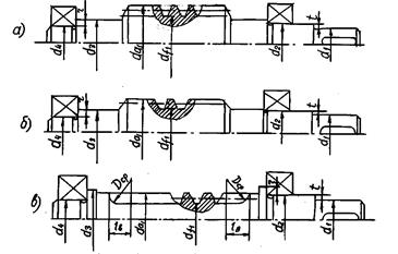 |
Fig.39. Design of a worm shaft: a) ; b) ;
One of the main requirements is the design of high rigidity of the worm. For this purpose, they try to make the distance between the supports as small as possible. The diameter of the worm shaft in the unthreaded part is set so as to ensure, if possible, free exit of the tool when processing turns and the required size of the thrust shoulder for the bearing.
With a relatively small diameter, the worm must be made according to Fig. 39, c. In this case, the height of the thrust shoulder in the places where the bearings are installed is coordinated with the outer diameter of the worm.
4.1.4. Tolerances of shape and location of surfaces
for worm gear parts
The rules for making drawings of cylindrical worms and worm wheels are established by GOST 2403-75. This standard defines the rules for indicating the parameters of ring gears on drawings. Other data necessary for the manufacture of these parts is shown in the drawing in accordance with the requirements of the ESKD.
The image of a cylindrical worm (Fig. 40) indicates: the diameter of the tops of the coil, the length of the threaded part of the worm along the tops , dimensions of the chamfers at the ends of the coil, roughness of the side surfaces of the coils Ö.
The image of the worm wheel (Fig. 40) indicates: the diameter of the tops of the teeth , ring gear width , distance from the base end T to the middle end plane of the wheel, largest diameter, radius of the surface of the tips of the teeth R, chamfer dimensions WITH or the radii of blunting of the end edges of the teeth, the roughness of the side surfaces of the teeth.
4.1.5. Case parts
worm gearboxes
The shape and dimensions of the housing parts are determined when configuring the gearboxes; The housing parts of worm gearboxes are designed in two versions: with small interaxial distances of mm, the housings are made one-piece, with mm - detachable.
In split housings, the parting line is made along the axis of the worm wheel shaft. In one-piece housings, it is necessary to provide for the possibility of assembling the gearbox, i.e. The side covers must be made of such a diameter through which the worm wheel can enter inside the gearbox.
Depending on the location of the worm relative to the wheel, worm gearboxes are made with a lower, side and upper worm arrangement. The lower position of the worm is usually used at a sliding speed of m/s. As for the dimensions of the elements of the gearbox housing itself, when designing it, you can use the recommendations that are given for the housing of a cylindrical horizontal gearbox (see Fig. 19). Tolerances of the shape and location of elements of body parts, see Fig. 24.