1. Introduction………………………………………………………………………………3 pages.
2. History of the appearance of the gear…………………………….4 p.
3. Types gears……………………………………………………………………7 pp.
4. Conclusion……………………………………………………………9 p.
5. Used literature…………………………………………….10 pages.
INTRODUCTION
The history of the appearance of the gear wheel dates back to ancient times and to this day plays an important role in our Everyday life and, especially, in the life of any engineer. Gear drives are used not only in mechanical engineering, but also in many other areas of production activity. So what is a gear wheel, without which it is impossible to imagine all our mechanisms?
The purpose of the study is to identify the meaning and significance of gear transmission in technology.
Object of study is a self-made wooden model corresponding to the chosen theme.
Based on the goal, the following research objectives were identified:
1. Explore various sources information about the subject of research;
2. Form a classification of gears and characterize their semantic meaning;
3. Examine a manufactured sample of a classic gear;
4. Draw conclusions from the work done.
History of the gear wheel A gear (gear, gear) is a wheel on the outer surface of which teeth are set at equal distances. The appearance of the gear wheel is one of the key inventions in the history of mankind. It's hard to imagine the mechanics modern devices without this element. The very principle of operation of the gear wheel and the gears associated with it is quite simple and even primitive, but it was this that gave rise to a huge number of more complex inventions. There is no specific author in history to whom this invention could be attributed, but historians have information that the first use of a gear wheel was by the scientist Ctesibius in his water clock (2nd century BC). It can also be found in sculptural works in Rome dating back to the work of Trajan's Column (early AD). Leonardo da Vinci's notes contain sketches of the use of gears in various mechanisms, including worm wheels, and of the two tooth shapes he proposes, one is very close to the modern one. Full implementation in engineering technology associated with scientific activities scientists Central Asia V IX-X centuries, the ancestors of modern Tajiks. The Danish scientist Olaf Roemer (1674) and the French scientist Charles Kalios (1766) were searching for tooth shapes that ensure smooth operation of the gear wheel. The French mathematician Philippe Lagère (1695) and the Swiss scientist Euler (early 18th century) worked in the field of involute tooth shapes. Based on these works, the English professor Willis gave the basis for practical application these tooth shapes in production. The invention of milling cutters by the American Joseph Brown (1864) made it possible to produce gear wheels with milled teeth, which
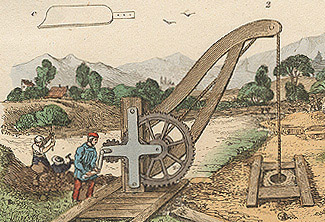
was necessary element in the introduction of replaceable gears with an involute tooth shape. A gear wheel serves to transmit rotation from one shaft to another, for which a gear wheel is mounted on both shafts and, moreover, so that the teeth of one wheel fit into the spaces (cavities) of the other. The ratio of the shaft revolutions per minute is called the gear ratio. The gear ratio can be determined by taking the ratio of the diameters of the gear or the ratio of the numbers of their teeth.| Fragment of an engraving depicting the drilling of an artesian well, 1836. |
 What was the impetus for the invention of the gear wheel? Of course, the need for industrial processing of manufactured products in agriculture. For example, a press made on the basis of the Archimedes lever had low efficiency, and with its use it was impossible to organize large-scale industrial production. But the gear wheel made it possible to multiply the force applied to it, turning translational motion into rotation and back. The gear wheel also led to the creation of the first mechanical clock in the 11th century AD. At that time, clocks were still powered by water energy. This is a “miracle of the East”, as well as perfumes, sugar, jewelry made of cut stones, glasses, colored fabrics, soft leather products, processed chemically, amazed Europe and enjoyed enormous success.
  If we talk about the practical benefits of this invention, then first of all it is worth highlighting its use in mining. In order to understand the scale of the breakthrough in this area, you can look at production statistics. The mining industry of the region in which the gear was introduced reached over seventy percent of the world's mineral production, including metals, precious and semi-precious stones. Another little known fact: this miracle invention gave rise to industrial production paper. Paper considered an invention
TYPES OF GEARS
The purpose of gears is to transmit rotational motion between shafts, which can have parallel, intersecting or crossing axes. Converting rotational motion into translational motion and vice versa is the task of rack and pinion gears. The force from one element to another is transmitted using teeth. A transmission gear with fewer teeth is called gear, the second wheel with a larger number of teeth is called wheel. In the case of the same number of teeth in a pair of wheels, the driving wheel is a gear, and the driven wheel is a wheel. Gears can be divided into cylindrical and bevel. There are three types of cylindrical wheels: spur, helical and chevron.
 Spur wheels are the most common type .
Their teeth are located in radial planes, and the contact line of the teeth of both gears is parallel to the axis of rotation. In this case, the rotation axes of both gears must also be located strictly parallel. Spur gears have the lowest cost, but, at the same time, the maximum torque of such wheels is lower than helical and chevron gears.
Spur wheels are the most common type .
Their teeth are located in radial planes, and the contact line of the teeth of both gears is parallel to the axis of rotation. In this case, the rotation axes of both gears must also be located strictly parallel. Spur gears have the lowest cost, but, at the same time, the maximum torque of such wheels is lower than helical and chevron gears. Helical wheels are an improved version of straight teeth. Their teeth are located at an angle to the axis of rotation, and their shape forms part of a spiral. The engagement of such wheels occurs more smoothly than straight teeth and with less noise. The contact area is increased compared to spur gears, so their force is also greater. But when a helical gear operates, a force arises directed along the axis, which necessitates the use of thrust bearings. In addition, an increase in the friction area of the teeth causes additional power losses due to heating, which must be compensated by the use of special lubricants. The main disadvantages are the occurrence mechanical force, which is directed along the axis, plus an increase in the friction area. There is a need to use bearings to install the shaft and use special lubricant. Helical wheels are used in mechanisms that require the transmission of large forces at high speeds, or have strict noise restrictions.

In many machines, the implementation of the required movements of the mechanism is associated with the need to transmit rotation from one shaft to another, provided that the axes of these shafts intersect. In such cases, bevel gears are used. There are types of bevel wheels that differ in the shape of the tooth lines: with straight, tangential, circular and curved teeth. Bevel wheels with straight teeth, for example, are used in automobile differentials, used to transfer torque from the engine to the wheels.
Conclusion
Humanity has come a very long way from the invention of a simple wheel to the appearance of the first prototypes gear wheels, which served for the first gears. The significance of the gear wheel turned out to be so great for all types of production that its appearance became a real symbol for many types of activities and for all technology in particular. The appearance of all things around us was greatly influenced by this key invention. Upon closer examination of the mechanism, it becomes obvious how simple it is in its operation and effective in performing a wide variety of technological tasks related to energy transfer. How important is it for someone starting out in technology to understand the role of his work? I think this awareness is necessary because no matter what field a student engineer enters, he will inevitably encounter the use of a wide variety of gears, as well as the need to maintain their operation. Since the Middle Ages, when its use ushered in the era of water and wind for our ancestors, the gear wheel has always participated in technological progress, reaching the present day and finding even deeper application in all our attributes of everyday life. There is every reason to assume that from -due to its basic and fundamental function, it is unlikely to be completely abandoned in the future. The entire human civilization owes its existence to the gear wheel.
References
Ginzburg E.G., Golovanov N.F. and others. Gear transmissions. Directory. M.: Mechanical Engineering, 1980. – 326 p.
G. Sarton, “Introduction to the history of science,” Williams and Wilkins, Baltimore, 1927
Materials of the All-Russian student scientific-practical conference"In the world scientific discoveries"/ - Ulyanovsk:, State Agricultural Academy named after. P.A. Stolypina, 2012, vol. III - 462 pp.
B.G. Gafurov. Tajiks. Dushanbe. "Irfon." 1989. T.1. pp. 33-55;
Gear transmissions. General information
A gear transmission is a three-link mechanism in which two movable gear links form a rotational or translational pair with a fixed link. The gear link of the transmission can be a wheel, a sector or a rack. Gears are used to convert rotational motion or rotational motion into linear motion.
All terms, definitions and designations used hereinafter related to gear transmissions comply with GOST 1653083 “Gear transmissions”, GOST 1653183 “Cylindrical gear transmissions” and GOST 1932573 “Bevel gear transmissions”.
Gearing is a higher kinematic pair, since the teeth theoretically contact each other along lines or points, with the smaller gear of the pair being called a gear, and the larger one a wheel. The spur gear sector is infinite large diameter called rack and pinion.
Gears can be classified according to many criteria, namely:according to the location of the shaft axes(with parallel, intersecting, crossing axes and coaxial);according to working conditions(closed operating in an oil bath and open operating dry or periodically lubricated);by number of steps(single-stage, multi-stage);according to the relative position of the wheels(with external and internal gearing);by changing the shaft rotation speed(lowering, increasing);according to the shape of the surface,on which the teeth are cut (cylindrical, conical);by circumferential speedwheels (low-speed at speeds up to 3 m/s, medium-speed at speeds up to 15 m/s, high-speed at speeds above 15 m/s);by tooth arrangementrelative to the generatrix of the wheel (straight, helical, chevron, with curved teeth);according to the shape of the tooth profile(involute, circular, cycloidal).
In addition to those listed, there are transmissions with flexible gears, called wave gears.
Main types of gears (fig.)with parallel axes: acylindrical spur, b cylindrical helical, h chevron, g with internal gearing;with intersecting axes: dconical spur, e conical with tangential teeth, f conical with curved teeth;with crossing axes: з hypoid and screw; To rack and pinion spur gear (hypoid and helical gears belong to the category of hyperboloid gears).
A gear whose axes are located at an angle of 90° is called orthogonal.
The advantage of gears lies primarily in the fact that, with the same characteristics, theymuch more compactcompared to other types of transmissions. In addition, gear transmissions have a higher efficiency (up to 0.99 in one stage), maintain a constant gear ratio, create a relatively small load on the shaft supports, have greater durability and reliability in wide power ranges (up to tens of thousand kilowatts), peripheral speeds (up to 150 m/s) and gear ratios (up to several hundred).
Disadvantages of gear drives: the difficulty of manufacturing precise gears, the possibility of noise and vibration with insufficient manufacturing and assembly precision, the impossibility of steplessly adjusting the speed of rotation of the driven shaft.
Gear drives are the most common types mechanical gears and are widely used in all branches of mechanical engineering, in particular in metal-cutting machines, cars, tractors, agricultural machines, etc.; in instrument making, watch industry, etc. The annual production of gear wheels in our country amounts to hundreds of millions of pieces, and dimensions they range from fractions of a millimeter to ten meters or more. Such a wide distribution of gears necessitates extensive research work on the design and manufacturing technology of gears and comprehensive standardization in this area. Currently, terms, definitions, designations, elements of gears and gears, basic parameters of gears, calculation of geometry, calculation of cylindrical involute gears for strength, tools for cutting teeth and much more have been standardized.
Main kinematic characteristic of any gear gear ratio, defined according to the standard asratio of the number of wheel teeth to the number of gear teeth and denoted and therefore
The definition of gear ratio remains the same as for other mechanical gears, i.e.
Energy losses in gears depend on the type of gear, the accuracy of its manufacture, lubrication and consist of losses due to friction in the gearing, in the shaft supports and (for closed gears) losses due to mixing and splashing of oil. Lost mechanical energy is converted into thermal energy, which in some cases makes thermal calculations of the transmission necessary.
Meshing losses are characterized by a coefficient, losses in one pair of bearings by a coefficient and losses due to mixing and splashing of oil by a coefficient. Overall efficiency of single-stage closed gear
Approximately = 0.96...0.98 (closed gears), = 0.95...0.96 (open gears), = 0.99...0.995 (rolling bearings), = 0.96.. .0.98 (sliding bearings), = 0.98...0.99.
Surfaces of interacting wheel teeth that provide a given gear ratio, are called conjugate. The process of transmitting motion in a kinematic pair formed by gears is called gearing.
Spur gear

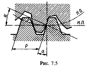
In Fig. depicted cylindrical wheel with straight teeth. The part of the gear that contains all the teeth is called the ring; The part of the wheel that fits onto the shaft is called the hub. Pitch circle diameter d divides the tooth into two parts tooth head height h a and tooth stem height h f, tooth height h = h a + h f. The distance between the same profiles of adjacent teeth, measured along an arc pitch circle, is called the circumferential pitch pitch of the teeth and is denoted R. The pitch of the teeth is made up of the circumferential thickness of the tooth s and width of the depression e. The chord length corresponding to the circumferential thickness of the tooth is called chord thickness and is designated. A linear value that is one time smaller than the circumferential step is called circumferential dividing module teeth, designated T and is measured in millimeters (from now on we will omit the words “circumferential division” in terms)
Tooth modulus is the main parameter of a gear.For a pair of wheels in mesh, the module must be the same.Tooth modules for cylindrical and bevel gears regulated by GOST 956360*. The values of standard modules from 1 to 14 mm are given in table.
Modules, mm
1st row 1; 1.25; 1.5; 2; 2.5; 3; 4; 5; 6; 8; 10; 12
2nd row 1.125; 1.375; 1.75; 2.25; 2.75; 3.5; 4.5; 5.5; 7; 9; eleven; 14
Note . When assigning modules, the 1st row should be preferred to the 2nd.
All main parameters of gears are expressed through modules, namely: tooth pitch
pitch diameter
The last formula allows you to determine the module as the number of millimeters of pitch circle diameter per one wheel tooth.

According to the standard reference contour for spur gears, tooth head height h a = t, tooth stem height h f = 1.25t. Tooth height cylindrical wheels
h = h a + h f = 2.25 m.
Tooth tip diameter
d a = m (z + 2),
dimple diameter
d f = m (z 2.5).
The distance between the ends of the wheel teeth is called the width of the rim. Contact between a pair of teeth on a spur gear theoretically occurs along a line parallel to the axis; the length of the contact line is equal to the width of the crown. During the operation of the transmission, a pair of teeth engages immediately along the entire length of the contact line (which is accompanied by an impact of the teeth), after which this line moves along the height of the tooth, remaining parallel to the axis.
Center distance of cylindrical gear with external and internal gearing
called the pitch distance between axes (minus sign for internal gearing). If the center distance differs from the pitch distance, then it is designated and w.
GOST 164381 establishes tolerances for cylindrical gears and gearstwelve degrees of precision,designated by numbers (first degree highest). For each degree of accuracy, standards are established: kinematic accuracy, smooth operation and contact of wheel teeth and gears.
In the process of manufacturing gears, errors in the pitch, thickness and profile of the teeth are inevitable, radial runout of the rim, fluctuations in the center distance with backlash-free engagement of the controlled and measuring wheels, etc. are inevitable. All this creates a kinematic error in the angles of rotation of the driven wheel, expressed linear quantity, measured along the arc of the pitch circle. Kinematic error is defined as the difference between the actual and calculated angle of rotation of the driven wheel. Kinematic accuracy standards regulate the tolerances for kinematic error and its components for a full revolution of the wheel. Smoothness standards establish tolerances for the cyclic (repeated many times during one revolution) kinematic error of the wheel and its components. Contact standards establish the dimensions of the total contact patch of the gear teeth (as a percentage of the tooth dimensions) and tolerances for the parameters affecting this contact.
In mechanical engineering, gears general purpose manufactured to 6x9 degrees of accuracy. Cylindrical spur wheels of the 6th degree of accuracy are used at peripheral wheel speeds of up to 15 m/s; 1st degreesup to 10 m/s; 8th degree up to 6 m/s; 9th up to 2 m/s.

Let us consider the forces acting in the engagement of a spur gear. With the contact of a pair of teeth in the pole shown in this figure P there is no sliding (and therefore friction), the engagement will be single-pair and the force interaction of the wheels will consist of transmission along the pressure line (normal NN ) strength normal pressure . Let us decompose this force into two mutually perpendicular components And , called respectively circumferential and radial forces, then
where engagement angle.
If the transmitted torque is known T and diameter d dividing circle, then
(since = 20°, then ).
Force , causes rotation of the driven wheel and bends the wheel shaft in the horizontal plane, the force G bends the shaft in a vertical plane.
Helical gears with oblique and chevron teeth

Helical gears are those in which the theoretical pitch line of the tooth is part of a helical line of constant pitch (the theoretical pitch line is the line of intersection of the side surface of the tooth with the pitch cylindrical surface). The tooth line of helical gears may have right and left direction of the helix. The angle of inclination of the tooth line is indicated.
Helical gear with parallel axes hasopposite direction of teethdriving and driven wheels and belongs to the category of cylindrical gears, since the initial surfaces of such gears represent the side surface of the cylinders. A transmission with helical gears, the axes of which are crossed, has the same direction of the teeth of both wheels and is called a helical gear, which belongs to the category of hyperboloid gears, since the initial surfaces of such gears are parts of a single-sheet hyperboloid of rotation; The dividing surfaces of these wheels are cylindrical.
U helical gears the contact lines are located obliquely relative to the tooth line, therefore, unlike straight teeth, oblique teeth do not engage immediately along the entire length, but gradually, which ensures smooth engagement and a significant reduction in dynamic loads and noise during transmission operation. Therefore, helical gears, compared to spur gears, allow significantly higher maximum peripheral wheel speeds. For example, helical wheels of the 6th degree of accuracy are used at peripheral speeds of up to 30 m/s; 7th degreeup to 15 m/s; 8th degree up to 10 m/s; 9th up to 4 m/s.
Normal pressure forcein the engagement of helical gears can be decomposed into three mutually perpendicular components (Fig. 7.10, b): circumferential force, radial force and axial force equal to:
where T transmitted torque; engagement angle.
Presence of axial force significant drawback helical gears. In order to avoid large axial forces in a helical gear, the angle of inclination of the tooth line is limited to values = 8...20°, despite the fact that the strength of the teeth, the smooth operation of the gear, and its load capacity increase with increase.

In modern gears, helical gears are predominant.
A cylindrical gear wheel, the width of which consists of sections with right and left teeth, is called a chevron gear. The part of the crown with teeth in the same direction is called a half-chevron. For technological reasons, chevron wheels are made of two types: with a track in the middle of the wheel(a) and without track (b). In a chevron wheel, axial forceson half-chevrons directed in opposite directions,are mutually balanced inside the wheel and are not transmitted to the shafts and shaft supports.Therefore, for chevron wheels, the angle of inclination of the teeth is taken in the range = 25...40°, as a result of which the strength of the teeth, the smooth operation of the transmission and its load capacity increase. Therefore, chevron wheels are used in powerful high-speed closed gears. The disadvantage of chevron wheels is their high labor intensity and manufacturing cost.
Geometric, kinematic and strength calculations of chevron and helical gears are similar.
Materials of cylindrical wheels
Materials for the manufacture of gears in mechanical engineering steel, cast iron and plastics; in instrument making gear wheels They are also made from brass, aluminum alloys, etc. The choice of material is determined by the purpose of the transmission, its operating conditions, the dimensions of the wheels and even the type of production (single, serial or mass) and technological considerations.
General modern trend in mechanical engineering the desire to reduce the material consumption of structures, increase the power, speed and durability of the machine. These requirements lead to the need to reduce the weight, dimensions and increase the load capacity of power gears. Therefore, the main materials for the manufacture of gears are heat-treated carbon and alloy steels, which provide high volumetric strength of the teeth, as well as high hardness and wear resistance of their active surfaces.
Performance criteria for gears and design load
Under the influence of normal pressure and friction forces, a wheel tooth experiences a complex stress state, but two factors have a decisive influence on its performance: contact stresses and bending stresses, which act on the tooth only while it is in engagement and are thusre-variables.


Repeatedly alternating bending stresses cause the appearance of fatigue cracks in the stretched fibers of the tooth base (the place of stress concentration), which over time lead to its breakdown (Fig. a, b).
Repeatedly variable contact stresses and friction forces lead to fatigue wear of the active surfaces of the teeth. Since the fatigue wear resistance of leading surfaces is higher than that of lagging surfaces, thenThe load capacity of the tooth heads is higher than that of the legs.This explains the peeling and chipping of material particles on the active surface of the tooth legs (Fig. V ) in the absence of visible fatigue damage to the heads. Fatigue wear of active tooth surfaces is typical for closed gears.
IN open gears ah and in gears with poor (contaminated) lubrication, fatigue wear is preceded by abrasive wear of the active surfaces of the teeth (Fig. d).
In heavily loaded and high-speed gears, in the contact zone of the teeth, heat, which promotes rupture of the oil film and the formation of metal contact, resulting in teeth jamming (Fig. d), which may result in the cessation of the relative movement of the transmission wheels.
So, The criterion for the performance of gears is the wear resistance of the active surfaces of the teeth and their bending strength.
Full text search:
Home > Abstract >Industry, production
1 Basic Concepts about gears
1.1 General information
In a gear drive, motion is transmitted by engaging a pair of gear wheels (Fig. 1, a - V). The smaller gear is called gear, more - wheelm. The term "gear" refers to both a gear and a wheel. Gear parameters are assigned index 1, wheel parameters - index 2. Gears are the most common type of mechanical transmission, as they can reliably transmit power from fractions to tens of thousands of kilowatts at peripheral speeds of up to 275 m/s. 
Rice. 1. External spur gears
Gear drives are widely usedin all branches of mechanical engineering and instrument making.
Advantages. 1. High reliability of operation in a wide range of loads and speeds. 2. Small dimensions. 3. Greater durability. 4. High efficiency 5. Relatively low loads on shafts and bearings. 6. Constancy of the gear ratio. 7. Easy to maintain.
Flaws. 1. Relatively high requirements for precision manufacturing and installation. 2. Noise at high speeds.
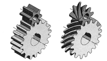
Classification.Depending on the relative positiongeometric axes of shafts gear transmissions are: cylindrical - with parallel axes (Fig. 1); finite - with intersecting axes (Fig. 2, A, b); screws - with crossing axes (Fig. 3). Helical gears are characterized by increased slip in engagement and low load capacity, and therefore have limited use.


Rice. 2. Bevel gears:a - straight-toothed;Rice. 3. Screwgear
b- with a circular tooth;broadcast
To convert rotational motion into translational motion and vice versa, a rack and pinion gear is used (Fig. 4), which is a special case of a cylindrical gearthat transmission. The rack is considered as a wheel whose diameter is increased to infinity.
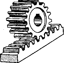

Rice. 4. Rack and pinion transmissionRice. 5. Cylindricalskaya straight-tootheddacha internalY.behindclinging
Depending on the location of the teeth on the wheel rim there are (see Fig. 1) gears: spur (a), helical (b), chevron (c) and s circular teeth(see Fig. 2, b).
Depending on the shape of the tooth profile transmissions are: involute, with Novikov gearing, cycloidal. Involute gearing is widely used in modern mechanical engineering..
In 1954, M. L. Novikov proposed a fundamentally new gearing, in which the tooth profile is outlined by circular arcs. This engagement is possible only with oblique teeth.
Cycloidal gearing is currently preserved in instruments and watches.
Depending on the relative position of the wheels Gear transmissions can be external (see Fig. 1) and internal (Fig. 5) gearing. External gear transmissions are discussed below as the most common.
Depending on the design There are open and closed gears. In open gears, wheel teeth run dry or are periodically lubricated with grease and are not protected from the influence of the external environment. Closed transfers are placed in dust- and moisture-proof housings (cases) and work in an oil bath (the gear is immersed in oil to a depth of ⅓ of the radius).
Depending on the number of steps there are gear transmissions odno- and mnogo-step e.
Depending on the relative nature of the movement of the shafts a distinction is made between row gears (Fig. 1) and planetary gears.
1.2 Basics of gear theory
The tooth profiles of a pair of wheels must be conjugate, i.e., a given tooth profile of one wheel must correspond to a very specific tooth profile of the other wheel. To ensure a constant gear ratio, the tooth profiles must be outlined with curves that satisfy the requirements of the basic gearing theorem.
Rice. 6. Scheme for the proof of the main theoremengagement
Basic linking theorem. To prove the theorem, consider a pair of mating teeth in mesh (Fig. 6). The profiles of the gear teeth and the wheel touch at point S, called the meshing point. The centers of rotation O 1 and O 2 are located at a constant distance a w from each other. The gear tooth, rotating with angular velocity w 1, exerts a force on the wheel tooth, imparting to the latter the angular velocity w 2. Let us draw through the point S the tangent TT and the normal NN common to both profiles. Circumferential speeds of point S relative to the centers of rotation O 1 and O 2:
v 1 = O 1 S w 1 and v 2 = O 2 S w 2
Let us decompose v 1 and v 2 into components v" 1 and v" 2 in the direction of the normal NN and components v"" 1 and v"" 2 in the direction of the tangent TT. To ensure constant contact of the profiles, it is necessary to comply with the condition v" 1 = v" 2, otherwise at v" 1 v" 2 the teeth will cut in. Let us drop the perpendiculars O 1 B and O 2 C from the centers O 1 and O 2 to the normal NN.
From the similarity of triangles aeS and BSO 1 v" 1 / v 2 = O 1 B / O 1 S,
![]()
From the similarity of triangles afS and CS0 2 v" 2 / v 2 = O 2 C / O 2 S, whence v" 2 = (v 2 /0 2 S) O 2 C = w 2 *O 2 C. Ho v" 1 = v" 2, therefore, w 1 * O 1 B = w 2 * O 2 C.
Gear ratio
u = w 1 / w 2 = O 2 C / O 1 B. (1)
The normal NN intersects the line of centers O 1 O 2 at point P, called the pole of entanglement. From the similarity of triangles O 2 PS and O 1 PV
O 2 C / O 1 B = O 2 P / O 1 P = r w1 / r w2 (2)
Comparing relations (1) and (2), we obtain
Thus, the main linking theorem is formulated: to ensure a constant gear ratio of gear wheels, their tooth profiles must be outlined along curves with a common normalNN, drawn through the point of contact of the profiles, divides the distance between the centersO 1 O 2 into parts inversely proportional to the angular velocities.
The engagement pole P maintains a constant position on the line of centers O 1 O 2, therefore, the radii r w 1 and r w 2 are also constant.
Circles of radii r w 1 and r w 2 are called initial circles. When the gear wheels rotate, the initial circles roll over each other without sliding, as evidenced by the equality of their peripheral speeds w 1 r w 1 = w 2 r w 2 obtained from formula (3).
Of the many curves that satisfy the requirements of the basic gearing theorem, the involute circle has received practical application in modern mechanical engineering, which:
a) allows you to obtain a tooth profile in a relatively simple and accurate way during the cutting process;
b) without violating the correct engagement, it allows some change in the interaxial distance a w (this change may arise as a result of inaccuracies in manufacturing and assembly).
Involute of a circle (Fig. 8.7). The involute of a circle is the curve described by point S of straight line NN, rolling without sliding along a circle of radius r b. This circle is called an evolute or main circle, and the rolled straight line NN is the generating line.
The nature of the involute gearing is determined by the properties of the involute.
The generating line NN is both tangent to the main circle and normal to all involutes it produces.
Two involutes of the same basic circle are equidistant *.
As the radius r b of the main circle increases, the involute becomes flatter and turns into a straight line as r b → ∞.
The radius of curvature of the involute at point S 2 is equal to the length of the arc S 0 B of the main circle. The center of curvature of the involute at a given point is on the main circle.
1.3 Manufacturing of gears
Gear blanks are produced by casting, die forging or free forging depending on the material, shape and dimensions. Wheel teeth are made by rolling, cutting, or less often by casting.
Rolling of teeth. Used in mass production. Preliminary shaping of the teeth of cylindrical and bevel wheels is carried out by hot rolling. The crown of the steel billet is heated with high frequency currents to a temperature of ~ 1200 ° C, and then rolled between knurled wheels. In this case, the teeth are squeezed out on the crown. To obtain wheels of higher accuracy, subsequent machining of the teeth or cold rolling - calibration is carried out.
Cold rolling of teeth is used with a modulus of up to 1 mm. Gear rolling is a high-performance method for manufacturing wheels, sharply reducing metal waste into chips.
Tooth cutting. There are two methods of cutting teeth: copying and rolling. The method of copying is to cut the cavities between the teeth modular cutters(Fig. 8): disk (a) or finger (b). After cutting each depression, the workpiece is rotated by an engagement step. The depression profile is a copy of the profile cutting edges cutters, hence the name - copying method. The copying method is low-productivity and inaccurate, and is used primarily in repair work. 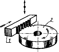
Rice. 7. Cutting diagram
teeth method
running-in
Cutting teeth using the rolling method is based on reproducing the engagement of a gear pair, one of the elements of which is the cutting tool - hob(Fig. 9, a), dolbyak(Fig. 9, b) or rack cutter - comb(see Fig. 7). The hob cutter has in its axial section


the shape of the tool rack. When cutting teeth, the workpiece and the cutter rotate around their axes, ensuring continuity of the process.
Cutting teeth with hobs wide applyfor the manufacture of


cylindrical wheels with external locationI eat teeth. To cut wheels with internal teeth, cutters are used. Spur and helical gears with a large engagement module are cut using combs.
Cutting the teeth of bevel wheels using the rolling method is done by planing (Fig. 10, a), milling (Fig. 10, b), with a tool with a straight-sided profile or cutting heads.
Tooth finishing. After cutting, the teeth of precision gears are finished by shaving, grinding, lapping or rolling.
Sh eve n g o v a n i e is used for fine processing of nezahardened wheels. It is performed with a tool - a shaver, which looks like a gear wheel with narrow grooves on the surface of the teeth. Rotating in engagement with the wheel being processed, the shaver removes hair-like chips from the wheel teeth with the cutting edges of the grooves.
Grinding is used for processing hardenedteeth Performed using grinding wheels using the copying or rolling method.


P r i t i r k u use for finishing hardened wheel teeth. This is done by lapping - a precision-made cast iron wheel using lapping abrasive pastes.
The roller is used to smooth out roughness on work surfaces teeth of unhardened wheels. For 1...2 minutes, the gear wheel is rolled under load with a high-hardness reference wheel.
1.4 Gear materials
The choice of gear material depends on the purpose of the gear and its operating conditions. Steel, cast iron and plastic are used as wheel materials.
Become. The main materials for gears are heat-treatable steels. Depending on their hardness, steel gears are divided into two groups.
F irst group - wheels with tooth surface hardness H ≤ 350 HB. Used in light and medium-loaded gears. The materials for wheels of this group are carbon steels 35, 40, 45, 50, 50G, alloy steels 40Х, 45Х, 40ХН, etc. Heat treatment- improvement carried out before cutting teeth.Wheels with hard tooth surfaces H ≤ 350 HB good run-in and are not subject to brittle fracture.
For uniform wear of the teeth and their better running-in, the hardness of the spur gear should be at(25...50) NV more wheel hardness.
For helical gearshardness NV the working surfaces of the gear teeth are desirable to be as large as possible.
The second group is wheels with surface hardness H>350 HB. High hardness of the working surfaces of the teeth is achieved by volumetric and surface hardening, carburization, nitriding, and cyanidation. These types of heat treatment make it possible to increase the load capacity of the transmission several times compared to improved steels.
Wheel teeth with surface hardness H>350 HB are not being worked in. For non-running-in gears, it is not necessary to ensure a difference in the hardness of the gear teeth and the wheel.
Surface hardening of teeth with heating by high frequency currents (h.f.) is advisable for gears with a module m ≥ 2 mm, working with improved wheels, due to good grinding of teeth. With small modules, a small tooth is calcined through, which makes it brittle and accompanied by warping. For hardening of t.v.h. steels 45, 40Х, 40ХН, 35ХМ are used.
Cementation is used for wheels whose dimensions must be minimal (aviation, transport, etc.). For carburization, steels 20Х, 12ХН3А, etc. are used.
Nitrogen plating provides particularly high hardness of the surface layers of the teeth. For gears in which there is no abrasive wear of the teeth, nitriding can be used. It is accompanied by low warping and allows you to obtain teeth of the 7th degree of accuracy without finishing operations. To increase the strength of the tooth core, the wheel blank is subjected to improvement. For nitriding, steels 40ХНМА, 40Х2НМА, 38ХМУА, 38Х2У are used.
Wheels with hardness H > 350 HB cut before heat treatment. The finishing of the teeth is carried out after the tarma treatment.
Selection of steel grades for gears. Without heat treatment, the mechanical characteristics of all steels are similar, therefore the use of alloy steels without heat treatment is unacceptable.
The hardenability of steels varies: high-alloy steels are the highest, carbon steels are the least. Steels with poor hardenability and large cross-sections of workpieces cannot be thermally treated to high hardness. That's why The steel grade for gears is selected taking into account the dimensions of their workpieces.

The characteristics of steels depend not only on the chemical composition and type of heat treatment, but also on the maximum dimensions of the workpieces: the diameter of the gear or worm workpiece D npe d and the largest section thickness of the wheel workpiece S prem.
Steel casting. Used in the manufacture of large gears (d a ≥ 500 mm). They use steel 35L...55L. Cast wheels are subjected to normalization.
Cast iron. Used in the manufacture of gears for low-speed open gears. Cast irons SCh18...SCh35 are recommended. The teeth of cast iron wheels wear in well, but have reduced bending strength.
Plastics. Used in high-speed, lightly loaded gears for gears operating in tandem with metal wheels. Gear wheels made of plastic are quiet and smooth. The most common are textolite, lignofol, caprolon, and polyformaldehyde.
1.5. Types of tooth destruction and performance criteria of gears
During operation, the teeth are subject to the forces of transmitted load and frictional forces. For each tooth, the stresses change over time in an intermittent zero cycle. Repeatedly alternating stresses are the cause of fatigue failure of teeth: their breakage and chipping of working surfaces. Friction in engagement causes wear and seizure of teeth.
Broken teeth. This is the most dangerous type of destruction. Fracture of teeth is a consequence of repeatedly alternating bending stress and overload occurring in the teeth. Fatigue cracks form at the base of the tooth on the side where the greatest stress occurs from bending.

tensile stress. Straight short teeth break off completely, and long teeth, especially oblique ones, break off along an oblique section (Fig. 12, a). Fatigue failure is prevented by calculating strength based on bending stressesσ f, applying correction, as well as increasing the accuracy of manufacturing and installation of the transmission.
Fatigue chipping of the working surfaces of the teeth.The main type of tooth failure for most closed gears. Occurs due to the action of repeatedly alternating contact stresses σ n. Destruction begins on the tooth stem in the circumpolar zone, where the greatest friction force develops, promoting plastic flow of the metal and the formation of microcracks on the surface of the teeth. The development of cracks is facilitated by the wedging effect of the lubricant, which is pressed in, and cracks in the teeth during engagement. The development of cracks leads to chipping of surface particles, the formation of small pits at first (Fig. 12, b), which then turn into cavities. When chipping occurs, the conditions for the formation of a continuous oil film are violated (oil is squeezed into the pits), which leads to rapid wear and scoring of the teeth. Dynamic loads, noise, and temperature increase.
When the tooth surfaces are hard H, limited chipping is observed, occurring only in areas with stress concentration. Once the teeth are worn in, this chipping will stop.
Progressive chipping occurs when the tooth surface hardness H > 350 HB; it gradually affects the entire working surface of the tooth legs.
Fatigue chipping of teeth is prevented by calculating strength based on contact stresses, increasing the hardness of the tooth surface, applying correction, increasing the degree of accuracy, and choosing the right type of oil.
No chipping is observed in open gears, since wear of the tooth surface outpaces the development of fatigue cracks.
Wear of teeth.The main type of destruction of the teeth of open gears. As the tooth wears out, it becomes thinner (Fig. 12, V), its leg weakens, the gaps in the engagement increase, which ultimately leads to breakage of the teeth. The destruction of teeth is preceded by increased noise during gear operation. Wear can be reduced by protecting against the ingress of abrasive particles, increasing the hardness and reducing the roughness of the working surfaces of the teeth, and reducing the sliding of the teeth through correction.
Teeth jamming. It consists of welding particles of one tooth to another due to a local increase in temperature in the meshing zone. The resulting growths on the teeth lift up the working surfaces of other teeth, furrowing them in the sliding direction (Fig. 12, G). Seizing of teeth is prevented by increasing the hardness and decreasing the roughness of the working surfaces of the teeth, applying correction, and correct selection of extreme pressure oils.
2 CYLINDRICAL HELICAL GEARS
1.1 General information
Cylindrical wheels, whose teeth are located along helical lines on the index cylinder, are called helical gears (see Fig. 1, b). Unlike a spur gear, in a helical gear the teeth do not engage immediately along their entire length, but gradually. The contact time of one pair of teeth increases, during which new pairs of teeth enter, the load is transmitted over a large number contact lines, which significantly reduces noise and dynamic loads.
The greater the angle of inclination of the tooth line β, the higher the smoothness of the engagement. For a pair of mating helical gears with external gearing, the angles β are equal, but opposite in direction. 
If there are no special requirements for transmissions, then the wheels are cut right-handed, and the gears- left.
For a helical gear (Fig. 13), the distance between the teeth can be measured in the face or circumferential (t – t) , and normal (P -n) directions. In the first case we obtain a circular step p t , in the second - a normal step R. The engagement modules will also be different in these directions:
Rice. 13. Geometric dimensions
helical gear
where m t and m are the circumferential and normal modules of the teeth.
According to Fig. 13
hence,
where β is the angle of inclination of the tooth on the index cylinder.
Normal modulem must comply with the standard and be the initial value for geometric calculations.
Pitch and initial diameters
A helical wheel is cut with the same tool as a spur wheel. The tooth inclination is obtained by turning the tool through an angle β. Oblique tooth profile V normal section matches the original contour of the tool rack and therefore coincides with the profile of the straight tooth of the module i.e.
Heights of the head of an oblique tooth h a and legs h f respectively equal:
Top diameter
Center distance
In a helical gear, by changing the value of the angle β, you can slightly change A w .
A spur gear can be considered as a special case of a helical gear, in which β = 0
1.2 Equivalent wheel
As mentioned above, the profile of an oblique tooth in a normal section A - A(Fig. 14) corresponds to the original contour of the tool rack and, therefore, coincides with the profile of the spur gear. Helical gears are calculated using the parameters of an equivalent spur gear.
Pitch circle of a helical gear in normal section A- A(see Fig. 14) forms an ellipse, the radius of curvature of which at the engagement pole
The tooth profile in this section almost coincides with the profile of a conventional spur gear called equivalent, pitch diameter of which
d v = 2 p v = d / cos 2 β = m t z / cos 2 β = mz / cos 3 β = mz v ,
where is the equivalent number of slo b e v
where z is the actual number of teeth of the helical gear.
From this formula it follows that as β increases, so does z v .
1.3. Meshing forces
In a helical gear, the normal force is F n makes an angle β with the end of the wheel (Fig. 15). Having spread out F n into components, we get:
radial force
Where F t = 2T 2 / d 2 - circumferential force;
axial force
When determining the directions of forces, the direction of rotation of the wheels and the direction of tooth inclination (right or left) are taken into account.


Axial forceF a additionally loads the bearings, increasing with increasingβ. For this reason for helical wheels acceptβ = 8...18°. The presence of axial forces in the meshing is a disadvantage of helical gearing.
1.4. Calculation of contact strength
Due to the inclined arrangement of the teeth, several pairs of teeth are simultaneously located in the helical gearing, which reduces the load on one tooth, increasing its strength. The inclined arrangement of the teeth reduces dynamic loads. All these features are difficult to take into account when deriving calculation formulas; therefore, the strength of helical gears is calculated using the formulas of equivalent spur gears with the introduction of correction factors into them. In terms of strength, the dimensions of helical gears are smaller than spur gears.
Design calculation. Similar to the calculation of a spur gear, the center distance for a steel helical pair
Where T 2 - in N * mm; [ σ ] n - in N/mm2.
Verification calculation. Similar to the calculation of a spur gear, contact stresses in the surface layer of helical teeth
where additionally according to the standard:
Z H ≈ 1.76 cos β - coefficient that takes into account the shape of the mating surfaces of the teeth. Average value Z H ≈ 1,71;
Coefficient that takes into account the overlap of teeth. Average value Z ε ≈ 0.8;
Z M = 275 N 1/2 / mm - for steel wheels.
Hence,
Where F t - in N; d 2 , b 2 - in mm; K H α - coefficient taking into account the distribution of load between the teeth. For helical wheels of 7...8th degree of accuracy:
TO N α = 1.04...1.09 at υ ≤5 m/s,
TO N α = 1.07...1.13 at υ = 5...10 m/s;
TO N β - coefficient of load unevenness across the width of the crown;
TO N υ - dynamic load coefficient. For helical gears it is recommended:
TO N υ = 1.02...1.06 for any tooth hardness and υ ≤ 10 m/s,
TO N υ = 1.1 with tooth hardness H ≤ 350 HB and υ = 10...20 m/s,
TO N υ = 1.05 with tooth hardness H > 350 HB and υ = 10...20 m/s.
1.5. Bending calculation
Similar to the calculation of a spur gear, the conditions for the bending strength of the gear teeth and the helical gear wheel
Where Y F - tooth shape coefficient, selected according to the equivalent number of teeth z v ;
Yβ = 1 - β /140° - coefficient taking into account the inclination of the tooth;
TO Fa- coefficient taking into account the distribution of load between the teeth. For helical wheels with υ ≤ 10 m/s and 7...8th degrees of accuracy TO Fa = 0,81...0,91;
TO Fβ - coefficient taking into account the distribution of load across the width of the rim;
TO F υ - coefficient taking into account the dynamic load in the gearing. For helical gears at υ ≤ 10 m/s:
TO Fυ = 1.2 with wheel tooth hardness H ≤ 350 HB,
TO Fυ = 1.l for wheel tooth hardness H > 350 HB.
1.7 Chevron cylindrical gears
The chevron wheel is a double helical wheel made as one piece(see Fig. 1, c). Due to the different directions of the teeth on the half-chevrons, the axial forces F a /2 are mutually balanced on the wheel and are not transmitted to the bearings (Fig. 16). This circumstance makes it possible to take chevron wheels tooth angleβ = 25...40°, which increases tooth strength and smooth transmission.
Chevron gears are made with a track in the middle of the wheel for the exit of the cutting tool (hob cutter in Fig. 16) or without a track (cut with a cutter or comb with a special sharpening, see Fig. 1, c). 
Chevron wheels without a track are cut on special low-productivity and expensive machines, so they are used less often than wheels with a track. Track width A= (10...15) m.
A chevron tooth requires a strictly defined axial position of the gear relative to the wheel, so the pairs are mounted in bearings that allow axial “play” of the shaft.
Disadvantage chevron wheels is the high cost of their production. Apply in powerful high-speed closed gears.
Geometric and strength calculation chevron transmission similar to calculations for helical gears. For a chevron transmission, the wheel rim width coefficient is ψ a = 0.4…0.8.
With strict parallelism of teeth and axes ABOUT 2 ABOUT 2 And O 1 O 1 straight teeth mesh along their entire length IN(Fig. 17, a)
If the wheel width IN having straight teeth, cut into a number of thin wheels 1,
2, 3, 4, 5
(Fig. 17, b) and rotate each of them on the axis relative to the previous one at a certain angle so that the tooth moves by arc s, then you get a wheel with a stepped tooth. When the wheels rotate, sections engage sequentially 1
- 1,
2-2, 3
- 3
etc. In the same sequence they will disengage. 
Taking an infinitely large number of infinitely thin wheels, we obtain an oblique (helical) tooth inclined to the axis of rotation at an angle β (Fig. 17, c). Helical teeth operate more smoothly than straight teeth because more teeth are in mesh at the same time for the same wheel width IN. A significant disadvantage of helical wheels is the presence of axial force R OS , aspiring
move the wheels along the shaft axis. From Fig. 17, V it is clear that the larger the angle β, the larger the
axial force R OS
at the same circumferential force R 0cr. In Fig. 17, V The direction of pressure of a gear tooth on a wheel tooth is shown. 
To eliminate axial load on the supports, two helical gears with teeth inclined in opposite directions are installed on the shaft. It should be borne in mind that if the longitudinal alignment of the wheels on the shaft is inaccurate, it may turn out that only one pair of teeth from two mating pairs of wheels will be in contact, for example the left one, as shown in Fig. 18 (as a rule, one of the shafts is made self-aligning relative to the other).
Axial force R OS tends to move the shaft to the left along with the wheel attached to it. To distribute circumferential force R okr equally on both wheels must be provided
longitudinal so-called installation gap e between the support and the side of the shaft.
After the gear (and shaft) is shifted to the left under the influence of force R OS The pressure on both halves of the wheel and gear is distributed equally.
1.8 Gear transmissions with meshing M. L. Novikova
Involute gearing, common in modern mechanical engineering, is linear, since the contact of the teeth occurs along a line (almost along a narrow area) located along the tooth (Fig. 19). Due to the small reduced radius of curvature, the contact strength of the involute gearing is relatively low, therefore, for modern powerful gears, the issue of increasing the load-bearing capacity of gears is important. 

M.L. Novikov proposed a new point linkage, in which the profiles of the wheel teeth in the end section are outlined along circular arcs(Fig. 20). The gear tooth is made convex, and the wheel tooth is made concave, which increases their reduced radius of curvature, significantly increasing the contact strength of the gear. 
In a Novikov gear, tooth contact occurs at the point and the teeth touch only when the profiles pass through this point (Fig. 20), and the continuity of motion transmission is ensured by the helical shape of the teeth. That's why Novikov gearing can only be helical
with tooth angle ß=15...20°. The position of the tooth contact point is characterized by its displacement from the pole, and the engagement line is parallel to the wheel axis. As a result of elastic deformation and running-in under load, the point contact turns into contact along a small area (Fig. 20). When the teeth roll mutually, the contact pad moves along the tooth at a high speed, approximately three times higher than the peripheral speed of the wheels, which creates favorable conditions for the formation of a stable oil layer between the teeth. For this reason Friction losses in the Novikov transmission are significantly less.
Novikov transmissions with one line of engagement are used - post-polar (less often - pre-polar) and with two lines of engagement - pre-polar. In gears with one line of engagement, the tooth profile of one wheel (usually a gear) is convex (see Fig. 20), and the other is concave. If the driving link is a gear with a convex tooth profile, then the point of contact is located behind the pole and the gear is called post-polar. If the drive is a wheel with a concave profile, then the gear becomes 
to the pole.
Subpolar transmission (Fig. 21) can be represented as a combination of prepolar and polar transmissions. The heads of the gear teeth and wheels have a convex profile, and the legs have a concave profile. This transmission has greater contact and bending strength.
To cut convex and concave teeth of a polar (prepolar) gear, you need different instruments. The teeth of the polar transmission are cut with one tool.
Essential not enough Novikov gearing is increased sensitivity to changes in center distance and load fluctuations.
The calculation of gears with Novikov gearing is carried out similarly to the calculation of gears with involute gearing, but taking into account their features.
3. REFERENCES:
N. G. Kuklin, G. S. Kuklina, “Machine parts.” Moscow, Higher School, 1987.
Y. M. Pavlov, “Machine parts.” Leningrad, Publishing House "Machine Building", 1969.