Worm gear gearboxes are one of the most common types of gearboxes.
Worm gear is the engagement of a worm with a worm wheel. A worm is a screw with a thread cut on it, which is close to trapezoidal in profile. A worm wheel is a helical gear wheel with a special tooth profile. When the worm rotates, the threads move along its axis and push the teeth of the worm wheel in this direction. The axis of the worm crosses at right angles with the axis of the worm wheel, the distance between them is the determining size of the gearbox. In Russian-made gearboxes, this size is integral part designation of the gearbox and determines its size. For example, Ch-80 - worm single stage gearbox with a center distance of 80 mm, and Ch-100, respectively, has a center distance of 100 mm.
Advantages of worm gears and drives built on them:
1. Since the input and output shafts of the worm gear are crossed, the drive based on it is usually better assembled in the machine, taking up less space compared to the spur gear ( we are talking about gearboxes with equivalent gear ratio and transmitted power).
2. The gear ratio of the worm pair can reach 1:110 (even more in special cases). Thus, worm-gear has much more potential to reduce speed and increase torque compared to other types of gears. Achieving gear ratios of this order using cylindrical gears possible only in a three-stage gearbox (or planetary). In a worm gear, only one stage can be used for this. This circumstance determines the relative simplicity and cheapness of worm gearboxes compared to cylindrical ones (again, we are talking about comparable gear ratios and transmitted powers). The flip side of this advantage, however, is a decrease in the efficiency of the worm gear with an increase in its gear ratio, for more on this, see the section.
3. Low level transmission noise, determined by the gearing features, allows the use of worm gearboxes in machines with high requirements for drive noiselessness. Here, however, we must not forget about the noise produced by engines and driven mechanisms.
4. Smooth running of the worm gear. Due to the peculiarities of the worm gearing, worm gears have a smoother ride compared to cylindrical gears.
5. Unique property worm gear - "self-braking" (another term for this phenomenon is "lack of reversibility"). Its essence is that in the absence of rotation of the drive shaft (worm), the driven shaft slows down, and it cannot be turned. This property begins to appear at gear ratios of 35 and above. It would be more correct to speak here not about the gear ratio, but about the angle of elevation of the worm, with a decrease in which, at a certain moment, self-braking occurs. Full self-braking is achieved in a gear in which the helix angle of the worm is equal to or less than 3.5°. However, gearbox manufacturers do not always provide information about this parameter in their catalogs, and developers have to operate with gear ratios. The described property, depending on the scope of the gearbox, can be both an advantage and a disadvantage. For example, it would be a design error to use a worm gear in the drive of, say, a seaming device, when refueling which requires manually turning the bobbin with the seamed sheet material, since the worm gearbox, even with a gear ratio of less than 25, is quite difficult to turn over the driven shaft. On the contrary, the use of a worm gearbox (with a large gear ratio of the worm pair) in the hoist drive makes it possible in many cases to refuse to install an additional braking device.
6. There are versions of worm gearboxes with a hollow output shaft. These gearbox options (also called “plug-in”) allow gearboxes to be mounted directly on the actuator shafts without the use of couplings or additional mechanical gears. This installation, in combination with the use of so-called "reaction rods" or flanged versions of the gearbox, simplifies the design and reduces the size of the drive:
Not only worm gearboxes, but also other types of gearboxes, with the possible exception of coaxial cylindrical gearboxes, where such an installation is impossible due to their design features, can have the described advantage. It should be noted here that sometimes the absence of a safety clutch between the output shaft of the gearbox and the shaft of the driven machine can lead to damage to the gearbox due to the application of an abnormal load on the output shaft that exceeds the rated output torque of the gearbox. In such cases, the task of the designer is either to ensure that such loads are not likely to be applied, or to protect the drive from them, for example, using a clutch.
The above applies to a greater extent to worm gears because of their self-braking.
Disadvantages of worm gears and drives built on them
1. The efficiency of a worm gearbox is lower than that of a cylindrical one. Moreover, the efficiency decreases with increasing gear ratio. This entails energy losses - a factor that in modern world under no circumstances should it be discounted. For example, the efficiency of a Ch-80 worm gear with a Russian-made 1:80 gear is 58%. The remaining 42% are losses due to irreversible energy dissipation. This disadvantage is due to the increased sliding friction of the worm turns against the teeth of the worm wheel compared to other types of gears. In this sense, the worm gear is similar to the “sliding screw-nut” gear, which is also not very efficient. During the running-in period under load for 200 ... 250 hours, the efficiency can be 90% of the nominal.
2. Heating. This is a consequence of the previous shortcoming. That kinetic energy that was not transferred by the worm gear is converted into heat. It is not for nothing that ribs are made on the cases of worm gears, making them look like batteries central heating. Some large worm gearboxes are supplied with fan impellers on the free end of the high speed shaft. In other cases, it is necessary to organize forced circulation oil in the gearbox housing. The foregoing applies to gearboxes with a large transmitted power (over 4 ... 5 kW). In cases with lower power, additional measures for heat dissipation are usually not required. However, the heating of the worm gear case during its operation always takes place.
3. Self-braking (for more details, see "advantages"). Its appearance is sometimes harmful - in cases where the output shaft needs to be turned without turning on the worm gear drive.
4. Limitations on transmitted power. The technical literature does not recommend using a worm gear with a transmitted power of more than 60 kW (source - Handbook of the designer-machine builder V. I. Anuriev, vol. 2, p. 606, edition 2001). Worm gears for over high power, however, do exist. These are mainly globoid worm gears used in special cases (for example, elevator and hoist drives). And yet, when choosing a gearbox for such power, it is recommended to give preference to cylindrical types reducers. As far as I know, leading foreign manufacturers worm gearboxes for the most part produce worm gearboxes for power transmission up to 15 kW.
5. Backlash of an output shaft. Such backlash exists in any type of gearboxes, however, in worm gearboxes, its value is usually larger and increases with wear.
6. The resource of worm gearboxes is considered to be lower than that of cylindrical ones. This is a very conditional statement, but due to the presence of increased sliding friction in engagement compared to other types of gearboxes, wear does occur. Russian manufacturers gearboxes provide the following data on the parameters of the working life of gearboxes with different types gears:
7. The operation of the worm gear under conditions of uneven loads on the output shaft, as well as with frequent start-stops, is not recommended.
Application of worm gears
The range of application is extremely wide. Conveyors, conveyors, hoists, pumps, agitators, gate drives, metalworking machines, including for milling. Where a budget solution is required to reduce the speed of the drive and increase the torque in the absence of significant shock loads and low switching frequency, put a worm gearbox there. However, this is still too categorical a statement. Without claiming absolute infallibility against the truth, I will nevertheless try to formulate basic recommendations for the use of worm gears:
1. If self-braking is not required, and the gear ratio of the gearbox must be more than 25, use helical-worm gearboxes. The efficiency of such a gearbox will be higher due to a reduction in the gear ratio at the worm stage. Accordingly, there will be savings in energy costs and an increase in the service life.
2. Do not install worm gearboxes in drives of mechanisms that are under shock loads. During long-term work with shocks, the worm gear may overheat, and its resource will sharply decrease. The author of these lines witnessed oil boiling in a gearbox transmitting 4 kW power after several hours of its operation as a drive for a rougher drum, which was subjected to periodic shock loading from a knife that cuts the tread blocks of worn tires.
3. Has great importance installation diagram of the gearbox in space. The basic and most recommended transmission for lubrication conditions is the scheme when the worm axis is at the bottom and the wheel axis is at the top:
Other orientation in space is possible, when ordering, carefully consider the conformity of the designation of the gearbox layout with reality! If there is a discrepancy, oil may leak from the gearbox, the worm may run “dry” or, conversely, be completely immersed in oil. All this leads to a sharp reduction in the resource. At top location worm, the technical literature recommends derating the rated output torque by 20%.
4. Torque arm or flange mount is preferred over foot mounted gearbox. See Benefits.
5. I do not recommend using worm gears in positioning systems. The backlash available in the gear can negatively affect the accuracy (here, of course, everything depends on the specific conditions - if the output shaft is connected, for example, to a lead screw with a small pitch, and the required positioning accuracy of the nut is ± 1 mm, a worm gearbox is quite suitable).
6. When choosing the type of gearbox in relation to the worm gear, it is always necessary to be aware of the possibility of self-braking and everything that follows from this property. Do not put a worm gear on the trolley wheelset drive if it needs to be rolled by hand from time to time. It will be hard to ride.
7. Before starting a new gearbox into operation under load, it is recommended to run it in idle mode (without a working load or with a reduced load) for 15 ... 20 hours to run in rubbing surfaces.
8. Worm gear V general case requires a thicker lubricant than other types of gearboxes.
From the very moment that mankind mastered the wheel, it became necessary to transfer torque from one element to another. Even the great Leonardo da Vinci tried to depict such mechanisms in his drawings. The invention of the internal combustion engine gave impetus to new inventions, including a mechanism capable of converting torque from one speed to another. However, only in our time people have invented such a mechanism, it is called a cylindrical gearbox. What it is? What types are there? What exactly does it serve?
What is a cylindrical gearbox
Name helical gearbox did not appear at all from the cylindrical shape of the unit. The gearbox owes its name to cylindrical pattern mechanism operation. Inside the gearbox are several gear wheels that have a cylindrical or conical shape.
The word reducer is a transliteration Latin word reducer, which means retracting (leading) back. This gives an idea of the basic ability of the gearboxes. The transmission in gearboxes can be direct, chain or gear.
A cylindrical gearbox is a mechanism designed to transmit and convert torque. This mechanism is able to effectively convert high angular velocity. The transformation takes place in more low speed. When connected directly to the structure of the motor, the gearbox is also called a cylindrical motor gearbox. The transmission of torque occurs in different planes and under different angle shafts to each other. In the parallel plane of movement of the shafts of gear cylindrical gearboxes, there are:
- spur gear and
- Helical spur gearbox
The spur gear is made with a straight tooth form of the rotary element. Due to this, the engagement process occurs along the entire length of the tooth. Such spur gears are used in gearboxes open type. Strong engagement provides high power, but leads to premature wear of the torque elements (for example, the teeth themselves). When calculating a spur gear, the increased noise that is created during the rotation of the gear teeth is also taken into account. There are single-stage spur gear, two-stage, three-stage and so on. Steps mean the number of gears in the gearbox.
Helical spur gearboxes are characterized by an indirect shape of the teeth, which allows for a gradual engagement of each successive tooth. Reduces noise and vibration. The efficiency factor increases. The rotation of the shaft with such a transmission occurs with less effort. A single-stage helical helical gearbox is distinguished, as well as a two-stage, three-stage, and so on.
Design features
Planar difference in the placement of the shafts is not significant. The main factors of difference are internal design features torque transmission. Among helical gearboxes constructively allocate:
- bevel-cylindrical reducer
- worm gear reducer

Bevel-helical gearbox
The bevel-helical gearbox is a classic type of spur gearbox. The main purpose of such a gearbox is to convert or change the speed of rotation of the shafts. The conical shape of the working parts also makes it possible to efficiently transfer torque from one shaft to another, regardless of the approach angle. The bevel type spur gearbox is characterized by high efficiency and reliability in operation. These properties of the aggregate directly affect specifications mechanism in which the gearbox is installed. For example, the performance depends on the number of gears in the mechanism. Therefore, single-stage spur gearboxes and multi-stage gearboxes are distinguished.
An illustrative example of such a gearbox is a horizontal cylindrical single-stage gearbox. This reducer is used for following conditions:
The speed of the spur gearbox must not exceed a nominal speed of 1800 rpm. The dimensions of such a gearbox are small and compact and weigh only up to 250 kilograms.
Worm-cylindrical reducer
The worm gear is a constructive variety classic helical gearbox. As a rule, this spur gearbox is assembled in a vertical plane and consists of a gear motor and a shaft to which it transmits torque. However, a horizontal version is also possible. This is done by direct fasteners, or through a special flange. Some characteristics of the mechanism operation depend on the type of attachment.
The direct connection option implies a rigid shaft run. This is possible thanks to the coupling. It connects the starting shaft with a special multi-start worm stage. Thus, the cylindrical gearbox receives an increase in efficiency without additional energy costs associated with starting the mechanism. However, compared to a bevel gear, this worm gear has a relatively low efficiency. Therefore, such gearboxes are used only for intermittent operation of the mechanism.
It is extremely rare for a worm gear to be found in two-stage spur gearboxes. The reason is the low efficiency and high cost of production. Three-stage spur gearboxes are more common, which structurally differ not only in the number of stages, but also in the presence of coaxiality.
Helical gear worm-spur type designed for the perception of high axial and radial loads. At the same time, the performance characteristics of the unit do not change. The gearbox works especially stably at low speed. The main advantage of such a torque transmission system is its relative noiselessness.

DC Helical Gearboxes
This subspecies of gearboxes is not innovative in terms of design. Its great advantage lies elsewhere. The DC gearbox is extremely reliable in terms of starting performance. This type of helical gearbox is characterized by stable operation during overloads.
The concept of coaxiality in spur gearboxes
The distance between the axles of the gearbox also plays an important role. So, for example, a two-stage coaxial spur gearbox is more reliable and productive. This is explained by the concept of alignment, that is, a smaller distance between the axes of the shafts (input and output) than the distance between the center gears (stages). Coaxial gearboxes are produced with a right angle of shaft approach.
The advantage of the coaxial system of gearboxes is the underloading of the high-speed shaft, which naturally increases its power, and hence the efficiency. Among the shortcomings, one can note some complexity in the design of the gearbox, especially its high-speed shaft.
Efficiency table of spur gearboxes
Application of spur gearboxes
Due to their positive performance, cylindrical gearboxes have found their application in: mechanical engineering, automotive industry. Gearboxes are used in drives of equipment using shafts. Mixers, extruders, shredders, machine tools for metal and other equipment.
As restrictions for the use of spur gearboxes can be called: the need to achieve smooth running mechanism, maintaining small dimensions with a large gear ratio of steps.
2.4 Design description of the spur gearbox
The gearbox consists of a massive cast-iron housing, nodes gear wheels and gears with supports, bearing caps and adjusting rings (Figure 2.2).
Figure 2.2 - The design of a two-stage cylindrical
gearbox with expanded scheme
FRAME serves to place gear parts in it, to fill in the lubricant of gears and bearings, protect them from contamination and to absorb the forces that arise during the operation of the mechanism. The housing must be sufficiently strong and rigid, since in the event of its deformation, the shafts are misaligned, which can lead to increased wear of the teeth due to uneven load distribution and even to breakage. To increase the rigidity, the body is reinforced with ribs located in the areas where the shaft supports are located. For ease of installation, the housing is made detachable. The parting plane is horizontal and passes through the axes of the shafts. Bottom part body 1 is called the crankcase, the top 2 is called the cover. The cover has a viewing window 3, closed by a rectangular cover with an outlet 4, which serves to equalize the pressure inside the gearbox housing with atmospheric pressure. In the crankcase 1 there is a plug 5 for draining the oil and a dipstick 6 for measuring its level. The crankcase and cover are fastened with bolts 7, 8.
GEARS serve to transmit rotational motion. The gearbox can have spur or helical gears. Compared to spur gears, helical gears have an increased load capacity and run more smoothly.
Wheels 10, 11 are mounted on the shaft by a fit that guarantees interference in mating, or keys 12, 13 are used. In some cases, gears are made integral with the shaft, obtaining the so-called gear shafts.
BEARINGS 14, 15, 16 serve to support the rotating shafts. The rolling bearing consists of an inner and outer ring with grooves for rolling balls, a set of balls (rollers) and a separator holding the balls (rollers) on
a certain distance from each other. The bearing is put on the shaft motionlessly and inserted into the housing with a clearance fit.
BEARING CAPS 17–21 serve to prevent dust and dirt from entering the housing and into the bearing units.
BOLT CONNECTIONS are used to fasten the housing and gearbox cover.
PINS 9 are designed to accurately fix the position of the cover relative to the gearbox housing when boring sockets for bearings together and when assembling the gearbox.
GEAR LUBRICATION at present, circulation and crankcase are widely used in mechanical engineering. In this gearbox design, crankcase lubrication is used, which is carried out by dipping gears in oil poured into the gearbox crankcase. Bearing lubrication can be thick (plastic), and carried out by spraying oil. The lubrication method is selected taking into account the circumferential speed of the gears.
2.5 Work order 
2.5.1
Disassembly of the gearbox and familiarization with the design and purpose
individual nodes
Disassembly of one of the gearboxes indicated by the teacher is carried out in the following order: unscrew the housing fastening bolts, lift the cover using a forcing bolt. Since the gearbox cover is a heavy part, the gearbox can be disassembled before starting work, which makes it possible to immediately begin to get acquainted with the design and purpose of the gearbox parts and assemblies (shafts, covers, adjusting rings, oil gauge dipstick, drain plug).
2.5.2 Definition geometric parameters high-speed or low-speed stages of a spur gear reducer
To solve this problem, it is necessary to carry out a series of accurate measurements using a vernier caliper with an accuracy of 0.1 mm and calculate the engagement parameters (Figure 2.3). To determine the parameters of each gear stage, it is necessary to count the number of gear teeth  and wheels
  each step, measure the diameters of the tops of the teeth
  , wheel width , center distance
  , outer diameters of bearings
  , internal diameters of bearings
  , bearing width
  .
.
Figure 2.3 - The main geometric parameters of the gearing
2.5.2.1
Gear module –
the main characteristic of the dimensions of the teeth. Module  - a value proportional to the step
  on a dividing cylinder, measured in millimeters:
  .
For helical gears define face and normal steps and modules.
.
For helical gears define face and normal steps and modules.
Step in end section  - this is the distance between the same points of the profiles of adjacent teeth, measured along the arc of the pitch circle of the gear.
normal step  - the shortest distance along the dividing cylinder between the same points of two adjacent teeth in a section perpendicular to the tooth:
 ![]() ,Where
- the angle of inclination of the teeth along the dividing cylinder. Accordingly, the normal module:
,Where
- the angle of inclination of the teeth along the dividing cylinder. Accordingly, the normal module:  .
.
For spur gears, the face and normal steps, and accordingly, the modules are the same. Modules are standardized (Table 2.1).
Table 2.1 - Standard toothing modules
| row number | |
| 1; 1,25; 1,5; 2; 2,5; 3; 4; 5; 6; 8; 10; 12; 16; 20; 25 |
|
| 1; 1,25; 1,375; 1,75; 2,25; 2,75; 3,5; 4,5; 5,5; 5,7; 9; 11; 14; 18; 22 |
 , for helical
  ,
, Where
– dividing wheel diameter, mm;  - number of teeth.
Since the wheel pitch diameter cannot be directly measured, the wheel modulus, as well as some of its geometric dimensions, can be determined indirectly using the expressions:
a) for spur gears 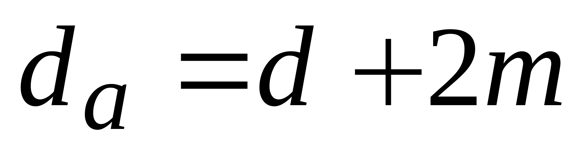 ,
,  ;b) for helical gears
 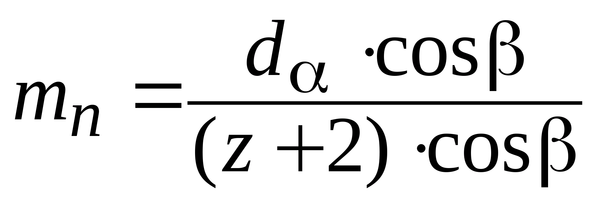 ;V)
;V) 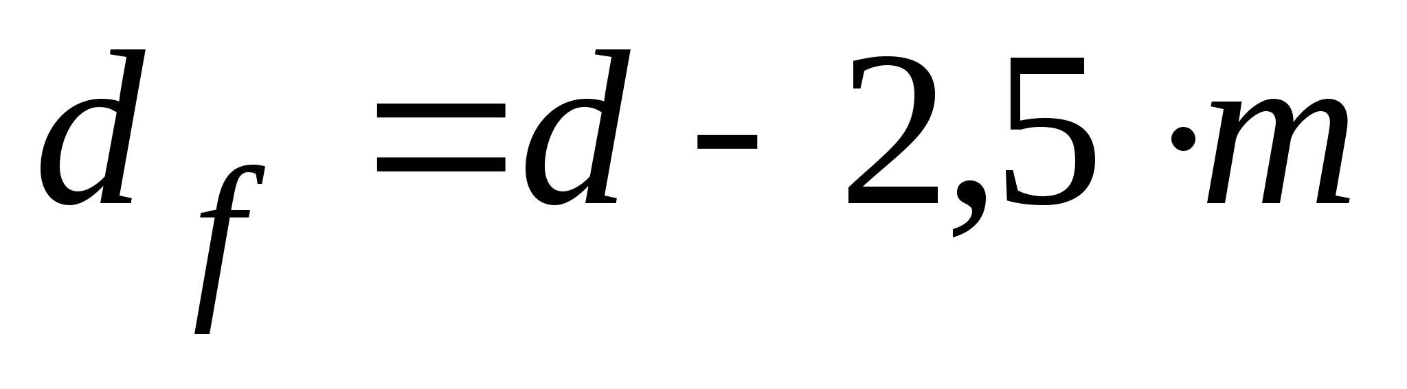 ;G) h =
2,25 m,Where
;G) h =
2,25 m,Where  –
wheel diameter at the tops of the teeth, mm;
–
wheel diameter at the tops of the teeth, mm;  –
wheel diameter along tooth cavities, mm; h –
tooth height.2.5.2.2 Gear ratio –
number ratio z 2 teeth larger wheel to number z 1 teeth smaller (gear)
–
wheel diameter along tooth cavities, mm; h –
tooth height.2.5.2.2 Gear ratio –
number ratio z 2 teeth larger wheel to number z 1 teeth smaller (gear)
 .
.
The gear ratio of the gearbox is equal to the product of the gear ratios of all its stages. For a two-stage gearbox:
 ,Where
  - gear ratio of the high-speed stage;
  - gear ratio of the low-speed stage. 2.5.2.3 Center distance of gears - distance between the axles of the driving and driven wheels –
determined by the formulas:
- gear ratio of the low-speed stage. 2.5.2.3 Center distance of gears - distance between the axles of the driving and driven wheels –
determined by the formulas: 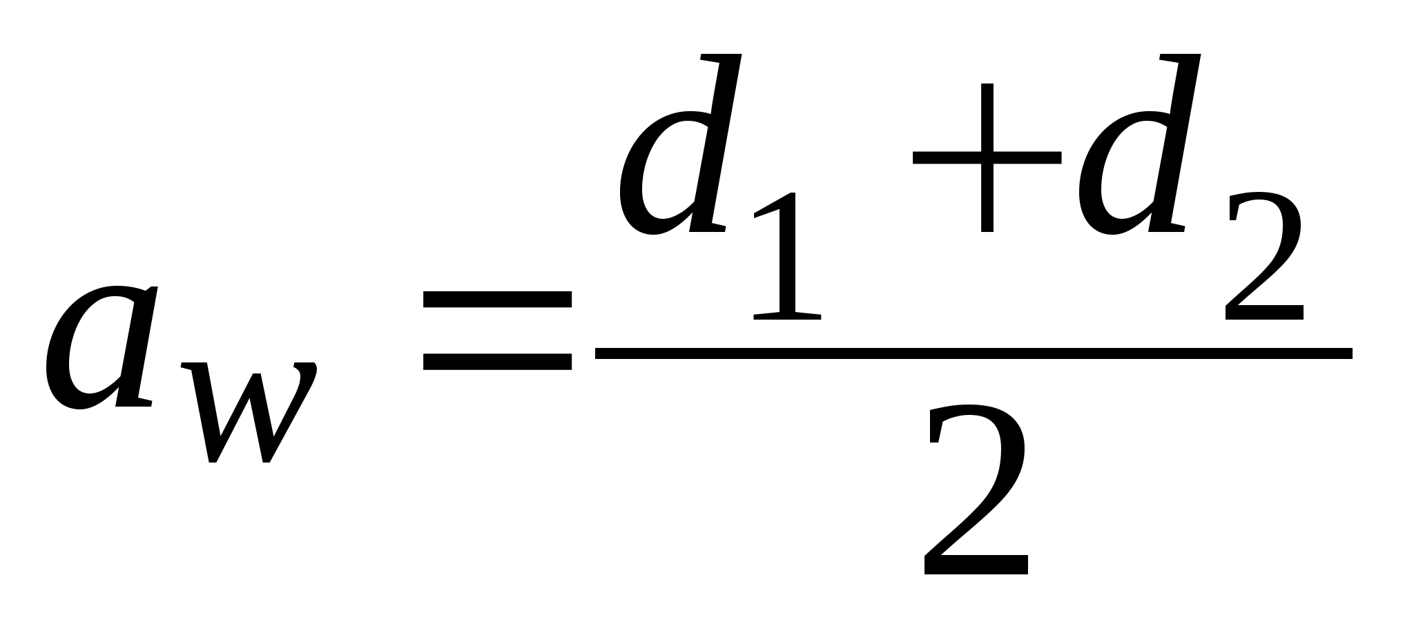 ,
,  where indices 1 and 2 respectively refer to the gear and wheel. The center distance of the transmission can be measured with a caliper, the angle of –
goniometer or calculate through trigonometric functions. The gear module can be determined by the formulas: a) for spur gears
where indices 1 and 2 respectively refer to the gear and wheel. The center distance of the transmission can be measured with a caliper, the angle of –
goniometer or calculate through trigonometric functions. The gear module can be determined by the formulas: a) for spur gears  ;b) for helical gears
  .
. Since the angle  in laboratory conditions it is difficult to determine accurately enough, the value
  may differ from the standard value. Having accepted the nearest standard value of the module from Table 2.1, the actual value of the angle (with an accuracy of seconds) and other geometric parameters of the gears are calculated in reverse order. Enter the results of calculations and measurements in Table 2.2.
Table 2.2 - Gearing parameters
| Options | fast step | Slow stage |
| Measurements: | ||
| Number of teeth | ||
Tooth tip diameter  | ||
| Wheel width | ||
center distance  | ||
| Bearing outside diameter | ||
| Bearing inner diameter | ||
| Bearing width | ||
| Estimated values: | ||
Gear ratios, ,  | ||
Total gear ratio  | ||
end module  | ||
| Tilt angle | ||
Normal module  | ||
| Diameters pitch circles wheels and gears | ||
| center distance | ||
| Height h tooth |
e) conclusions and conclusions.
3 LABORATORY WORK #2.
STUDY
BELT DRIVE CHARACTERISTICS
(4 hours)
Goal of the work: experimental determination of the dependence of a belt drive on the load (torque on the driven pulley), belt tension, gear ratio u.
Equipment : special installation; caliper, ruler.
3.1 General information
Belt transmission refers to friction transmissions with a flexible connection. The transmission (Figure 3.1) consists of a driving 1 and a driven pulley 2, wrapped around by a belt 3, a tensioner 4. The load is transferred by friction forces arising between the pulley and the belt due to the tension of the latter. Depending on the shape cross section transmission belts are flat-belt(Figure 3.1 b), round-belt(Figure 3.1 V), wedge(Figure 3.1 G),polyclinic(Figure 3.1 d).
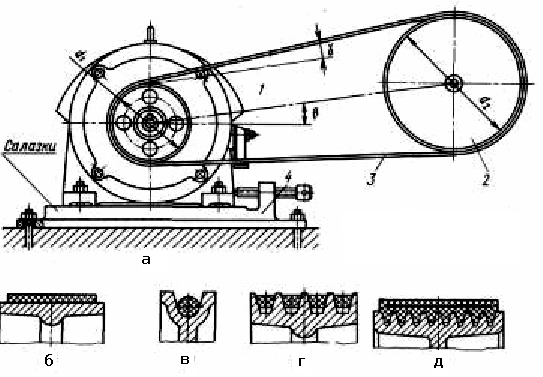
Figure 3.1 - Belt drive scheme
Benefits of a belt drive:
simplicity of design and low cost;
Ability to transmit power over long distances;
smooth and quiet operation;
reduction of vibration due to the elastic draw of the belt.
Disadvantages of a belt drive:
large dimensions;
low belt durability;
heavy loads on shafts and supports from belt tension;
inconstancy of the gear ratio due to the elastic slippage of the belt.
A belt drive is used in combination with other gears at high-speed drive stages.
Transmitted power - up to 50 kW, belt speed v= 5…50 m/s.
The main geometric characteristics (see Figure 3.1) of belt drives are:
1) center distance a ; subsequently center distance A specified at the final belt length;
2) effective length belt l ;
3) wrapping angle small pulley belt 1 .
3.1.1 Forces in the transmission and stresses in the belt
To create friction between the belt and the pulley, a pretension is applied. F 0 .
When applying workload T 1 the tension of the driven branch is reduced to a value F 2 , leading rises to a value F 1 :
F 1 = F 0 + DF; F 2 = F 0 – DF,
F 1 + F 2 = 2F 0 ;
circumferential force on the pulley:
F t = F 1 –F 2 .
Solving the last two equations together, we get:
F 1 = F 0 + F t / 2; F 2 = F 0 –F t / 2 .
When the belt runs around the pulleys, a centrifugal force arises in the belt:
F v = r Av 2 ,
Where A- cross-sectional area, m 2; r – material density, kg/m3; v- belt speed, m/s.
The tension forces of the belt branches load the shafts and bearings (Figure 3.2 A).

Figure 3.2 - Forces in the branches of the belt: A) T1<0; b) T1 >0
resultant force F n = 2F 0 sin ( a / 2).
Usually the value F n at 2 – 3 times the size F t .
During the operation of the belt drive from the acting forces, stresses arise in the material of the belt. The maximum tension in the belt occurs at the place where it runs onto the small pulley. Since the stress changes in magnitude when the belt is moved, the material of the belt breaks down due to fatigue over time, and maximum bending stresses occur here.
3.1.2 Belt slip. Pulling capacity of belt drives
When the movement is transmitted by the belt, the belt slips along the surface of the pulley. The slippage increases as the load increases. In the limit, slippage of the belt may occur and the transmission of movement will stop.
Slip is characterized by the slip coefficient E. In this case, the gear ratio:
u= 1 / 2 = d 1 / d 2 ( 1 - E) ,
where 1 , 2 – angular speed of rotation of pulleys; d 1 , d 2 – pulley diameter.
Value E depends on the load, the angle of the belt around the pulley and on the belt tension.
3.2.1 Device and principle of operation of the installation
The main elements of the installation design are shown in Figure 3.3.
On the cast base 1 of the installation are placed: a bracket 2 of the balancing system of the electric motor and a stand 15 with a load device. On the bracket 2, the electric motor housing 4 is balanced in ball bearings.
A driving two-stage pulley 8 is installed on the motor shaft.
The driven pulley assembly is mounted on a stand 15. A slider 20 is installed in the guides in the upper part of the stand. A load device 10 is attached to the housing, the shaft of which is articulated with the shaft of the two-stage driven pulley 11. The driven pulley shaft is mounted in the housing on two ball bearings. Lever 12 is attached to the body, when loaded, a moment of rotation is created relative to the axis, as a result of which the body, together with the shaft of the driven pulley, can move in the direction from the drive pulley, thereby creating additional belt tension.
With the help of the handle 13, the slider 20 is moved along with the body, due to which the preload of the belt is created.
Handle 14 fixes the slider in the guides with the selected pre-tensioning of the belt. From the side opposite to the driven pulley, a lever is attached to the shaft of the load device, which, with its end, creates a force applied to the spring. The amount of deformation of a flat spring is measured by indicator 27 installed in bracket 9.
Collectors of contact devices are fixed on the shafts of the driving and driven pulleys. The signals taken from the collectors of contact devices make it possible to determine, using counters 19 and 23, the number of revolutions of the driven and driving shafts. Installed on panel 16: switch 26 of the general power supply of the installation, engine switch 25, speed controller 24, counter of revolutions of the input shaft 23, counter of revolutions of the driven shaft 19, switch of control circuits of counters 22, switch of signals from contact devices 21 to counters, switch of the excitation circuit of the load device 18 and the excitation current regulator of the load device 17.
A ground terminal is installed on the rear side of the base of the device and a cable with a plug at the end is brought out to connect the device to a power source.
The load device is a magnetic powder brake, the principle of which is based on the property of a magnetized medium to resist the movement of ferromagnetic bodies in it.
A liquid mixture of mineral oil and iron powder is used as a magnetized medium in the design.
Machine parts
and applied mechanics
Laboratory works
Teaching aid
publishing house
Irkutsk State Technical University
Machine parts and applied mechanics. Laboratory works: teaching aid / comp. : VC. Eremeev, Yu.N. Gornov, A.G. Osipov, A.I. Pisarev. - Irkutsk: Publishing house of ISTU, 2013. - 102 p.
The educational and methodological manual meets the requirements of the Federal State Educational Standard-3 of the enlarged groups of specialties: 150000 Metallurgy, mechanical engineering and material processing; 220000 Automation and control; 160000 Aviation and rocket and space technology; 190000 Vehicles in the areas of training 150400 Technological machines and equipment, 151000 Design and technological support of automated machine-building industries, 220300 Automated technologies and production, 220400 Mechatronics and robotics, 150200 Machine-building technologies and equipment, 160100 Aircraft industry, 190205 Hoisting and transport, construction, road machines and equipment. For each work, theoretical material is given in a compressed form, revealing the principle of functioning of the node under consideration. The purpose and procedure for performing the work are given. The laboratory equipment used and the rules for its safe operation are described in detail. A report form for each work is given.
Designed for students of all forms of study in the above areas.
Reviewer
dr. tech. Sci., Professor, Head of the Department of Mechanical Engineering Technology, ISTU, Member of the UMO for Mechanical Engineering Technology
D. A. Zhuravlev
© Irkutsk State
Technical University, 2013
Lab 1
DISASSEMBLY, ASSEMBLY AND INVESTIGATION OF GEAR
REDUCER
Goal of the work: familiarization with the design of cylindrical gearboxes and the purpose of its parts, drawing up a kinematic diagram of the gearbox, determining the geometric parameters of the engagement by measuring and calculating them; determination of gear accuracy.
Gear Description
A mechanism consisting of gears (bevel, worm, etc.) with a constant gear ratio, designed to reduce the angular velocity and increase the torque, is called a gearbox.
The most widespread two-stage gearboxes
(65% of the total). A two-stage spur gear reducer is carried out according to the developed (Fig. 1, a and b) or coaxial (Fig. 1, c) schemes. The most common is a simple expanded scheme (Fig. 1, a).
Rice. 1. Kinematic diagrams of gearboxes
However, the asymmetric arrangement of the wheels leads to an increase in the load concentration along the length of the tooth. Shafts in such gearboxes must have increased rigidity. Reducers with a forked low-speed stage (see Fig. 1, b) can significantly reduce the stress concentration and increase the angle of inclination of the teeth.
Coaxial gearboxes (see Fig. 1, c) are convenient when assembling the drive. In such gearboxes, the gears on the input and output shafts are located symmetrically, but the intermediate shaft is significantly lengthened.
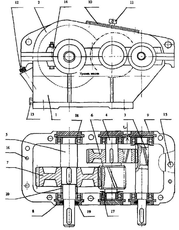
Rice. 2. Reducer cylindrical
For laboratory work standard gearboxes are used, made according to the detailed scheme. General form gearbox is shown in fig. 2. The gear housing is detachable, the body parts are cast from gray cast iron grade SCH12 or SCH15 (GOST 1412-85). The bearing seats on the housing 1 and cover 2 have lugs (lugs), which allows the tightening bolts 15 to be brought closer to the bearing holes, thereby increasing the rigidity of the bolted connection. Two pins 16 are designed to fix the position of the gearbox cover relative to the housing. IN upper belt The housing has holes for forcing screws to facilitate the disassembly of the gearbox. Gear high speed transmission 3 is made integral with the input shaft of the gearbox, the gear wheel 6 is mounted with an interference fit on the intermediate shaft-gear 4. The low-speed gear has a similar design solution.
Output shaft material 5 - carbon structural steel (GOST 1050-88) grades 35, 45, 50 or alloyed structural steel (GOST 4643-71) grades 40X, 45X, etc. For the manufacture of gear shafts
3, 4 and gear wheels 6, 7, high-quality carbon structural steels of grades 40, 45, 50.50G, etc. or alloy steels of grades 40X, 45X, 40XH, etc. are accepted.
The shafts are supported by radial or angular contact bearings 18. They perceive the radial and axial loads that occur in helical gears. Axial fixation of all shafts is made according to the "spread" scheme: the ends of the inner rings of the bearings abut against the shoulders of the shaft or the ends of the spacer bushings 20, the outer ends of the outer rings abut against the ends of the bearing caps. There are through 8 and blind 9 bearing covers. If non-adjustable bearings (radial or angular contact ball bearings) are installed, then a gap is provided between the end of the cover and the outer ring of the bearing to compensate for thermal deformations WITH= 0.2...0.5 mm. The inner rings of the bearings are installed on the shafts with an interference fit in order to avoid running in the ring of the shaft neck, flaring of the seating surfaces and contact corrosion. The outer rings are assembled to a fit that provides zero or little clearance required during installation, and also allows axial movement of the bearing with thermal elongation of the shaft.
Gears are lubricated by dipping them in oil poured into the housing.
The capacity of the oil bath must be at least 0.35...0.5 l per 1 kW of transmitted power in order to avoid rapid aging of the oil and agitation of wear products. The oil level should ensure that the high-speed wheel is immersed in oil by approximately two tooth heights. The oil level is controlled by a rod oil indicator 12. Oil is poured through the inspection hatch 10. To drain the used oil, there is an oil drain hole closed by a plug 13 in the lower part of the housing. Seals 19 are installed in the through covers to eliminate oil leakage and ingress of dust and dirt into the gearbox.
The bearings are splash lubricated. Oil-drop rings 17 are installed on the high-speed and intermediate shafts on the side of the gears in front of the bearings, which protect the bearings from overfilling with oil.
Vent 11 allows you to equalize the pressure inside the housing with atmospheric pressure.
Determination of the main parameters of the gearbox
The gear ratio of the gearbox is the ratio of the number of teeth of the wheel to the number of teeth of the gear
The gear ratio of the gearbox is equal to the product of the gear ratios of the steps
u = u 1 ∙u 2 .
center distance a ω(Fig. 3) in gears without displacement of the original contour is equal to the dividing center distance
![]() ,
,
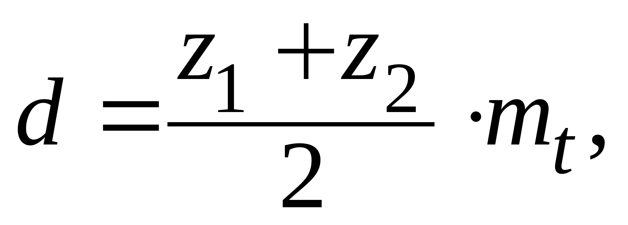
Where d1 And d2 are the pitch diameters of the gears and wheels, respectively (Fig. 4).
Pitch diameter d = z∙m t ,
Where m t- end module.
Tooth tip diameter d a = d+2m n .
Tooth cavity diameter d f = d - 2.5m n ,
Where m n - normal module.
Figure 5 shows a plan of a helical original rail, on which lines of teeth are plotted, making an angle with the axis of the cut wheel β called the angle of inclination of the line of the tooth. The direction of inclination is determined by the direction of the helix of the tooth. If the tooth line rises from left to right (see the gear tooth in Figure 3), then the tooth is right. In this case, the direction of view is along the axis.
Tooth pitch ratio p n , measured in a section by a normal plane p-p, to the number π is called a normal module tn. The normal modulus is calculated for the original generating circuit. It must match standard value. Modules, mm, according to GOST 9563-81:
Row1 1.25 1.5 2 2.5 3 4
Row2 1.375 1.75 2.25 2.75 3.5 4.5
Tooth pitch ratio pt measured in section by the end plane
t-t is called the end module.
From fig. 5 follows .

Rice. 3 Helical gear Fig 4. Gear
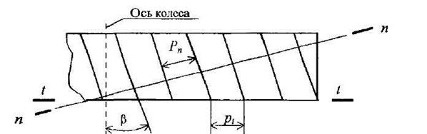
Figure 5. Original helical rack
©2015-2017 site
All rights belong to their authors. This site does not claim authorship, but provides free use.