The interaction forces of the teeth are usually determined at the gearing pole. The load in engagement distributed over the contact area is replaced by the resultant F n normal to the tooth surface. It is convenient to represent this force in the form of components F t, F r, F a.
District force F t = 2 10 3 T/d ;
Axial force F a = F t tgβ
On the driven wheel the direction of the circumferential force F t coincides with the direction of rotation, on the driving wheel it is opposite to it.
Radial force F r = F R tgα = F t tgα / cosβ
The vectors of radial forces for wheels with external gearing are directed towards the axle, and for wheels with internal gearing - away from the axis gear wheel.
2. Calculation of spur gears for contact strength.
Tooth contact strength is the main criterion for most gears.
In gears without bias a w = (d 2 ± d 1)/2 = d 1 (u ± 1)/2
From where d 1 = 2 a w /(u ± 1) d 2 = 2a w u/(u ± 1),
where u = d 2 /d 1 – gear ratio.
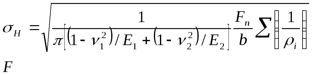
The highest contact stress in the engagement zone is determined by the Hertz formula:
ν 1.2 – Pausson coefficients of materials of contacting bodies;
E 1.2 – elastic moduli of materials;
ρ 1.2 – radii of curvature of contacting surfaces;
b – contact line length (cylinder length)
The force F n is determined by the circumferential force taking into account the load factor. According to the results of experiments for calculations, the total length
b= l Σ contact lines are determined taking into account the end overlap coefficient: F n = K H ·Ft/cosα ; b = l Σ = 3b 2 /(4 - ε α).
The contact of the teeth is considered as the contact of two cylinders with the radii of curvature of the tooth profiles in the engagement pole:
Let's substitute the obtained values into the Hertz formula:
Σ(1/ρ i) = 1/ρ 1 ± 1/ρ 2 = (ρ 2 ± ρ 1)/(ρ 2 ρ 1)
=
Let's denote:
Z E =  - coefficient taking into account the elastic properties of materials of mating wheels; Z E = 191.6 MPa 0.5 for steel wheels at E 1 = E 2 = 2.1 10 5 MPa and ν 1 = ν 2 = 0.3.
Z H =  - coefficient taking into account the shape of the mating surfaces of the teeth in the engagement pole; Z H = 2.5 at α w = 20 o.
Z ε =  - coefficient taking into account the total length of contact lines; Z ε = 0.9 for spur gears at ε α = 1.6.
In this case, we obtain the calculated dependence in the form provided for by the standard: 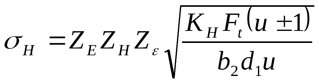 ;
;
Replacing F t = 2 10 3 T 1 /d 1 in the formula; b 2 = ψ bа а w; d 1 = 2a w /(u ± 1) , we consistently obtain
Solving for a w we get a w = 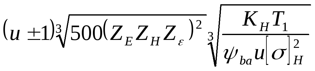 ;
;
Designating K a = 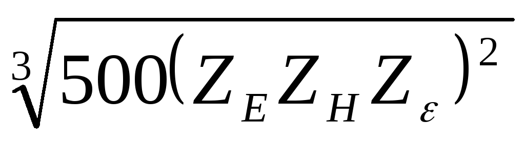
The formula for the design calculation of cylindrical gears has the form: a w = K a 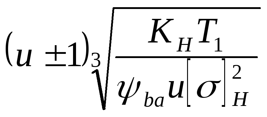
According to the standard:
for spur gears K a = 450 MPa 1/3;
for helical and chevron gears K a = 410 MPa 1/3.
In general, the center distance of a helical spur gear is approximately 20% less than the center distance of a spur gear.
When calculating cylindrical gears, the value of the wheel ring gear width coefficient ψ wa = b 2 /a w is specified. Depending on the location of the gear relative to the supports, take: ψ VA = 0.2 ... 0.5.
Formula for verification calculation:
Coefficient values Z σ for cylindrical steel gears:
straight teeth Z σ = 9600 MPa 1/2;
helical and chevron Z σ = 8400 MPa 1/2
During design calculations, the value of the design load coefficient K N = 1.3 is set approximately. During the verification calculation, its updated value is determined based on the known dimensions and degree of transmission accuracy.
When performing a verification calculation, it is desirable to achieve equality σ N = [σ] N, since when σ N > [σ] N– it is possible to underestimate the transmission resource, and when σ N < [σ] N overestimation of its mass. The simplest way to achieve σ Н = [σ] Н is to change the width of the ring gear b 2. The contact strength of wheel teeth depends on the material and size of the gear and does not depend on the module and number of teeth individually. According to the conditions of contact strength for a given a w, the module and number of teeth can have different values, but subject to the following conditions: 0.5m(Z 1 + Z 2) = a w and u = Z 2 /Z 1.
3.Calculation of cylindrical gear teeth for bending strength.
The second of the two main criteria for the performance of gears is the bending strength of the teeth. When deriving the calculated dependence, the following assumptions are made:
There is one pair of teeth in mesh.
The tooth is considered as a cantilever beam loaded with a concentrated force F n applied to the tooth at its apex
Force F n acts at an angle (90 – α /) to the axis of symmetry of the tooth; angle α / is slightly larger than the engagement angle α w. To identify the stressed state of the tooth, the force F n is transferred along the line N 1 N 2 of engagement until it intersects with the tooth axis in the t.c. and is decomposed into components directed along the tooth axis and perpendicular to it (Fig. 2).
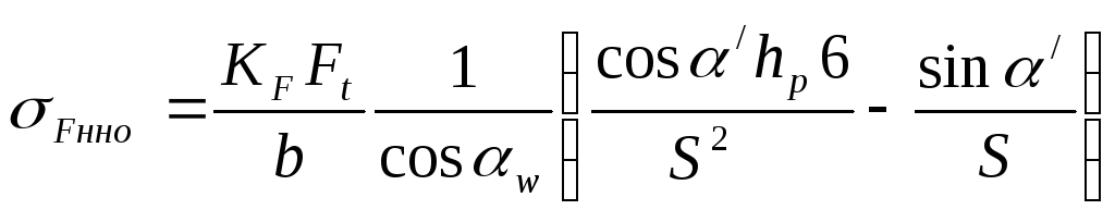
Under the action of a component directed along the axis, compressive stresses σ compress = F n sinα / /bS act at the base of the tooth, the diagram of which is shown in Fig. 3 (b is the length of the tooth). Points A and B determine the position of the dangerous section of the tooth during bending. The tooth in this section is loaded with a bending moment M = F n h p cosα / , causing the action of stresses σ and: to the left of the axis - tension, to the right - compression. The total stresses σ Fnom on the side of stretched fibers (t.A) have lower values than on the side of compressed fibers (t.B). However, tensile stresses are more dangerous. Voltages without taking into account concentrators are called nominal.
Let us determine the nominal bending and compression stresses in t.A:
where W x = bS 2 /6 is the axial moment of resistance of the dangerous section AB.
Expressing the force F n through the circumferential force F t taking into account the load factor K F , we obtain:
 , where F n = K F F t /cosα w
The dangerous section AB is located in the zone of stress concentration caused by a change in shape on the transition surface at the base of the tooth. The local stress in this section exceeds the nominal stress by α T times:
σ F = σ F nom α T, where α T is the theoretical stress concentration factor.
Taking into account this voltage in the dangerous section
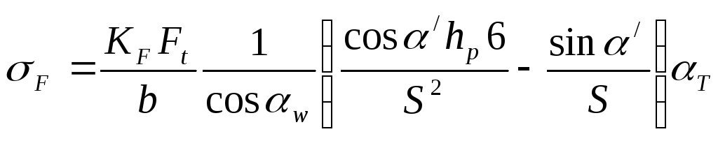
The bending arm h p and the tooth thickness S are expressed through the module m
Where 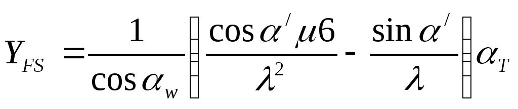 - coefficient taking into account the shape of the tooth and stress concentration. Selected by table or graph.
Taking into account the strength condition σ F< [σ] F , получим формулу для verification calculation of gears based on bending stresses:
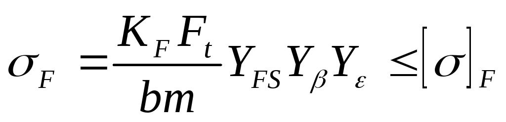 ,
,
where Y β is a coefficient taking into account the angle of inclination of the tooth Y β = 1 – β/100, provided Y β > 0.7; Yε - coefficient taking into account the overlap of teeth Y ε = 1/ε α = 1/1.6 = 0.65.
For spur gears: Y β = 1; Y ε = 1 with a degree of accuracy of 8.9;
Y ε = 0.8 with degrees of accuracy 5, 6, 7. Y FS 1 > Y FS 2 since the gear tooth at the base is thinner than the wheel tooth. To ensure approximately equal bending strength of the mating teeth, the gear is made of a stronger material. Condition for equal bending strength of gear and wheel teeth: [σ] F 1 /Y FS 1 ~ [σ] F 2 /Y FS 2
Replacing F t = 2 10 3 T 1 /d 1 u d 1 = 2a w /(u ± 1), we obtain a formula for checking the calculation of teeth based on bending stresses and solve the resulting inequality with respect to m: 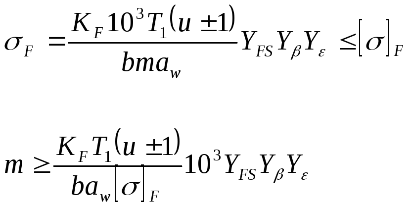
The width b 1 of the gear rim is made 2 - 4 mm larger than the width b 2 of the wheel to compensate for possible axial displacement of the gears due to assembly inaccuracy. This is important when grinding in the teeth, when a harder gear overlaps the width of a less hard wheel.
Taking b = b 2 and denoting K m = 10 3 Y FS Y β Y ε, we obtain the calculated dependence for determining the minimum value of the tooth modulus
m 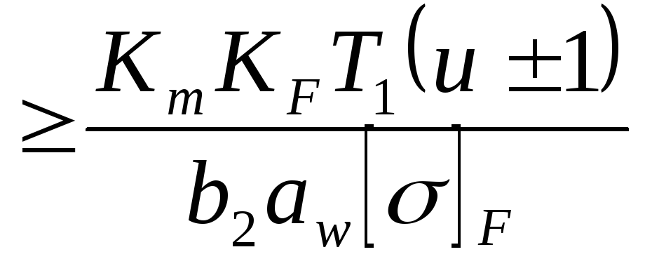 ,
,
where K m = 3.4 10 3 – for spur gears;
K m = 2.8 10 3 – for helical gears.
Instead of [σ] F, substitute the smaller of [σ] F 1 u [σ] F 2 into the formula.
Features of geometry and operating conditions of helical gears
The axis of the hob cutter, when cutting the teeth of a helical cylindrical gear, makes an angle β with the end plane of the wheel. Therefore, in a plane normal to the direction of the tooth, all its dimensions are standard. In a helical gear, the distance between the teeth can be measured in the front or circumferential, (t – t) and normal (n – n) directions. In the first case, the circumferential step p t is obtained , in the second – normal step p. The engagement modules are also different in these directions. :
m t = p t /π , m n = p/ π , where m t ; m n – circumferential and normal modules.
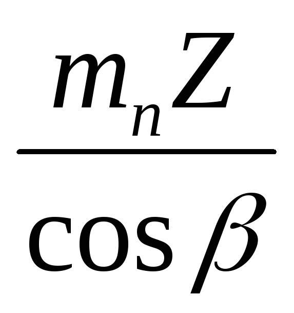
p t = p/ cosβ, hence, m t = m n / cosβ. A normal module must comply with the standard.
For a wheel without offset, the pitch d and initial d w diameters are:
d = d w = m t Z = m n Z/ cosβ
In addition to the end overlap, helical gears also provide axial overlap .
Axial overlap coefficient ε β = b 2 /p x, where p x is the axial pitch equal to the distance between the same points of two adjacent teeth, measured in the direction of the gear axis (Fig.)
Geometric features determine differences in operating conditions helical gear.
1. The driven wheel tooth engages starting from the apex, first increasing and then decreasing in length contact line when moving it from the head of the tooth to the stem. The entire length of the tooth does not work immediately; it burns in better and faster.
2. The contact time of one pair of teeth increases, during which new pairs of teeth engage; the load transmits a large number of contact lines, which significantly reduces noise and dynamic loads. The greater the angle of inclination β of the tooth line, the higher the smoothness of the engagement.
3. The load along the length of the contact line is distributed in proportion to the total stiffness of the gear teeth and wheel.
4. In a helical gear, 2-3 pairs of teeth are involved in meshing simultaneously. Therefore, the total length of the contact line l Σ braid is greater (by about 30%) than in a spur l Σ straight
l Σ cos = b 2 /(Z 2 ε cosβ b) ; l Σ straight = b 2 /Z 2 ε.
Coefficient Z ε takes into account the total length of the contact line:
For spur gears Z ε =
where ε α is the end overlap coefficient.
5. The relationship between the radii of curvature of the contacting teeth in a helical gear is more favorable: Σ(1/ρ i) braid = cosβ b Σ(1/ρ i) straight
All other things being equal, contact stresses in helical gearing are less in value than in spur gearing.
The concept of an equivalent wheel.
The profile of an oblique tooth in the normal section n – n coincides with the profile of a spur gear. Helical gears are calculated using the parameters of an equivalent spur gear:
m n - module; Z v - number of teeth. The tooth profile coincides with the profile of a conventional spur gear called equivalent, pitch diameter d v = m n Z v .
d v = 2ρ v = d/cos 2 β = m t Z/cos 2 β = m n Z/cos 3 β, where ρ v is the radius of curvature.
From the equality m n Z v = m n Z/cos 3 β the equivalent number of teeth follows:
Z v = Z/cos 3 β.
With an increase in the inclination angle β of the tooth line, the equivalent parameters increase, helping to increase the transmission strength.
Σ(1/ρ i) = 1/ρ 1 ± 1/ρ 2 = (ρ 2 ± ρ 1)/(ρ 2 ρ 1) =
Let's denote:
Z E =
-
Z H =
Z ε =
;
Replacing F t = 2 10 3 T 1 /d 1 in the formula; b 2 = ψ bа а w; d 1 = 2a w /(u ± 1) , we consistently obtain
Solving for a w we get
and w = ;
Designating K a =
a w = K a
, where F n = K F F t /cosα w
h p = μm and S = λm, where μ and λ are coefficients that take into account the shape of the tooth. Then
Where -
, where Y β
m
DESIGN CALCULATION OF A CYLINDRICAL GEAR
When designing a gear transmission, it is more convenient to determine not the stresses, but the basic geometric parameters. Center distance:
a w = (u + 1) 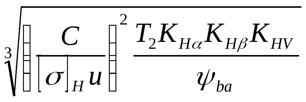 = , mm
where u is the gear ratio;
T 2 - torque on the wheel;
C is a coefficient that takes into account the mechanical properties of mating gears:
310 – for spur gears;
335 – for spur bevel gears;
270 – for helical cylindrical and bevel gears;
[σ] H - permissible contact stress, depending on the material and heat treatment of the gears and on the duration of the gear operation
Gears are made from rolled products or forgings from high-quality structural carbon or alloy steels with a carbon content from 0.1 to 9.6% with various types of heat treatment; for large wheel sizes (diameter more than 500 mm), steel casting is used. For spur gears made of improved or normalized steels with a hardness of no more than HB 350, the hardness of the working surface of the gear tooth should be 20 - 50 units greater than the hardness of the gear tooth. For non-spur gears, the difference in the hardness of the gear and wheel reaches 100 units or more, which increases the load capacity of the transmission in terms of contact strength.
Under a significant but quiet load, continuous hardening can be carried out; under a large and dynamic load, the inner part of the tooth should be viscous, and the outer high-strength; under a low dynamic load, the entire tooth can be viscous. If the transmitted power is large, then to reduce the weight and dimensions of the transmission, wheels with a higher surface strength should be used, i.e. the teeth must be solid or surface hardened, carburized, cyanidated and... Such teeth must be ground or lapped, therefore the degree of accuracy must be high. Wheels with chevron teeth are not hardened and are not ground.
Permissible contact stresses for gear and wheel:
where [σ] Р 0 – permissible contact stress corresponding to the basic number of loading cycles N NO (selected according to table 1)
Z R – coefficient that takes into account the roughness of the working surfaces of the teeth (for 7th class of roughness –1; for 6th class of roughness – 0.95)
Z V – coefficient taking into account the influence of peripheral speed and hardness (determined from the Z V – V graph for hardness HB≤ 350 and HB > 350)
K НL – durability coefficient K Н L = 
where N HO is the base number of loading cycles
N HE – equivalent number of wheel loading cycles
N HE = 
where T i max is the maximum long-term torque
T i – moments in load steps corresponding to the number of loading cycles N i (load change graph)
N i = 60n i t hi K K(w)
where n i is the shaft rotation frequency under the action of torque T i, min -1;
t hi - duration of load T i , in hours;
K K – number of engagements of the calculated wheel.
[σ] Н =  =
=
After the definition, you should check the fulfillment of the condition:
[σ] N ≤ 1.23 [σ] N min
With increasing reliability for helical gears, the value of [σ] N can be taken equal to the smaller of the two [σ] H1 and [σ] H2
K Нα – coefficient taking into account the uneven distribution of load between the teeth; for spur wheels 1; for helical teeth on schedule;
K Нβ - coefficient taking into account the uneven distribution of load along the length of the contact line - determined from a graph or table;
K НV - dynamic coefficient, taking into account the influence of transmission accuracy, tooth hardness and peripheral speed - is determined from the table;
Ψ wa – gear width coefficient
Ψ wa = b/a w Ψ bd = b/d
The choice of values of ψ ba and ψ bd significantly affects the quality of transmission - its efficiency, dimensions, requirements for manufacturing and assembly technology; with an increase in the gear rim width coefficient, the load concentration increases. During the design calculation, the value ψ va is specified:
0.125…0.20 – for spur gears of gearboxes;
0.20…0.35 – for spur gears of gearboxes;
0.20…0.50 – for helical wheels;
0.40…0.80 – for chevron gears.
For each subsequent gearbox stage, ψ va increases by 20–30% compared to the previous one.
Standard values:0.100; 0.125; 0.160; 0.20; 0.250; 0.315; 0.40; 0.50; 0.630; 0.80; 1.0; 1.25
After determining the center distance, the nearest standard value is taken: 40; 50; 63; 71; 80; 90; 100; 112; 125; 140; 160; 180; 200; 225; 250; 280; 315; 355; 400; 450; 500; 560; 630.
After adjusting the parameters and coefficients A test calculation for contact endurance is performed:
σ Н = 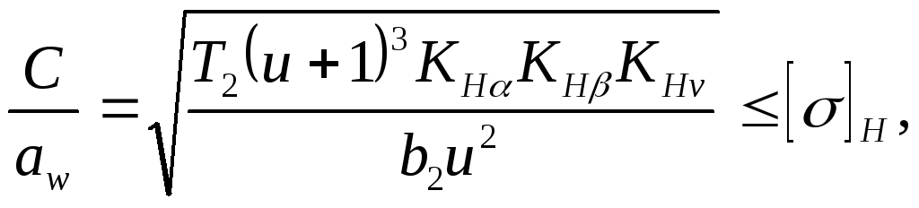 MPa
MPa
Here, if the contact stress is no more than 5...6% higher than the permissible one, or the underload does not exceed 10%, then the calculation is considered satisfactory.
Checking contact strength under short-term overloads:
σ Н max = σ H 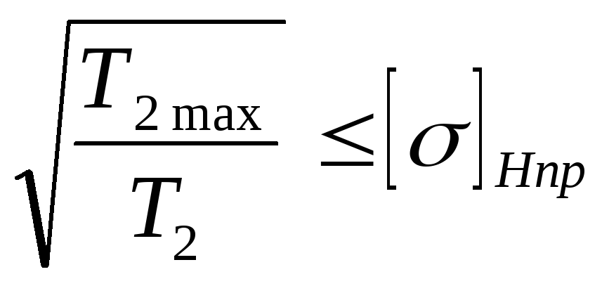 , MPa
, MPa
where [σ] Npr – ultimate voltage for contact strength:
at H ≤ HB 350 [σ] Npr = 3.1σ T
H > HB 350 [σ] Npr = 41.3HRC
Bending endurance test:
σ F = 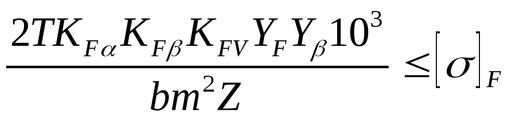 , MPa
, MPa
where T is the torque on the wheel being tested, N.m.
Z – number of teeth of the wheel being tested;
K F α - load coefficient, taking into account the distribution of load between the teeth (for spur gears K = 1; for helical gears with an average end overlap coefficient ε α = 1.5 and 8 degrees of wheel accuracy
K Fβ - coefficient taking into account the uneven distribution of load across the width of the rim (table)
K FV - coefficient taking into account dynamic loads (table)
Y F - tooth strength coefficient, determined by the equivalent number of teeth
Z V = Z/cos 3 β
β – tooth inclination angle in helical (8 0 ... 20 0) and chevron (25 0 ... 40 0) gears;
Y β - coefficient taking into account tooth inclination at β< 40 0
Y β = 1 – β/140 0
m - gearing module (for helical gears m n - normal module)
m = m n = (0.01 … 0.02)a w
The wheel tooth module must be selected as minimal as the outer diameters of the workpieces increase with its increase, but not less than 1.5 ... 2 for power transmissions
Determine the number of wheel teeth:
Z 1 = 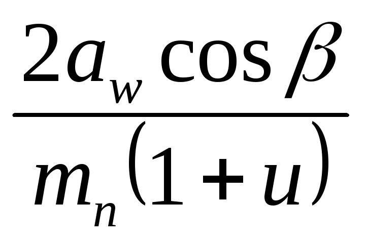 Z2 = uZ1
Minimum permissible value of Z 1, without the risk of cutting the tooth stem, for uncorrected wheels: Z min ≥ 17cos 3 β
Allowable stress during testing calculations for the endurance of teeth in bending: [σ] F = [σ] F 0 K FL Y R Y M
where [σ] F 0 – permissible bending stress corresponding to the basic number of cycles of stress changes N FO (table)
K FL – durability coefficient, depending on the ratio of the base and equivalent numbers of loading cycles
KFL= 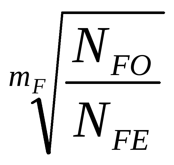
N FO = 4 10 6 – basic number of cycles
NFE = 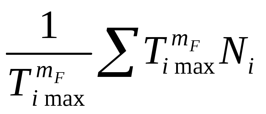 - equivalent number of bending cycles
m F - degree, m F = 9 – for steel wheels with an unpolished surface with hardness HB > 350 and for cast iron wheels; m F = 6 – for wheels with hardness less than HB350
If N FE > N FO = 4 10 6 then we accept K FL = 1
Y R – coefficient taking into account the roughness of working surfaces (1 – for ground and milled surfaces; 1.05 – carburization, nitriding; 1.2 – polished with normalization or improvement)
Y M = 1 for d ≤ 300 – coefficient taking into account the wheel diameter.
Definition geometric parameters cylindrical wheels
Diameter pitch circle:
2.Ring gear width
for gear b 1 = ψ ba ·a w + 5
for wheel b 2 = Ψ ba a w
3.Diameter of teeth tips d a = d + 2m n
4. Diameter of depressions d f = d – 2.5m n
5. Peripheral speed V = 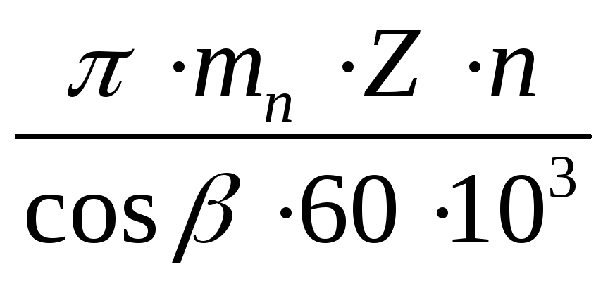
Page 2
Cylindrical gears are compact and have important property: They impart uniform rotation to the driven wheel while uniform rotation of the drive wheel.
Spur gears are designed to transmit rotation and torque between two parallel shafts. Cylindrical gears are spur, helical and chevron with external and internal gearing. Rack and pinion gears are also classified as cylindrical.
Spur gears are designed to transmit uniform rotational motion. For speed we obtain the equation v dS / dta, where a is a constant. If the acceleration j is zero, then there are no dynamic loads. In reality, due to inevitable meshing errors, significant dynamic forces appear, which often exceed the payload many times over.
Spur gears are designed to transmit uniform rotational motion.
Cylindrical gears are used mainly for transmitting high powers; this does not exclude the use of cylindrical gears for medium and low power. Bevel gears (like worm gears) are used for medium and low power.
The simplest cylindrical gear with external gearing is shown in Fig. 1.5. The mechanism converts the rotational motion of one wheel / into the rotational motion of another wheel 2 with a different rotation frequency and torque. Gears with external gearing transmit rotation by changing the direction of rotation.
Cylindrical gears of external gearing can be produced by the rolling method and the single division method on gear hobbing, gear planing or gear shaping machines.
Cylindrical gears of external and internal gearing of an involute profile are: spur, helical with spiral teeth (helical), single, block, chevron, multi-row helical and multi-row chevron. Bevel gears of an involute profile are: straight-toothed, helical-toothed, with curved teeth, and herringbone.
Given a cylindrical gear drive: a 450 mm, accuracy degree 7 according to all accuracy standards, interface type C.
Through cylindrical gears, the main camshaft 22 is driven into rotation (see Fig. 4.25, a), from which the rotation is transmitted to the cams of the drive mechanisms for turning and transferring workpieces and the ejector 16 from the dies. This fastening ensures that the knife is pressed against the end of the cutting matrix as the cutting force increases.
There are cylindrical gears with external and internal gearing. Cylindrical internal gears can be spur or helical. They are widely used in aircraft, transmissions passenger cars, complex planetary mechanisms, mainly where the interaxial distances are small.
For cylindrical gears, six (five for t 1 mm) classes of deviations of the interaxial distance are established, designated in descending order of accuracy by numbers from I (I) to VI.
Lecture 14.
Cylindrical gears.
The transmission of a continuous motion from one shaft to another with a given gear ratio is most often carried out using gear mechanisms. Gear mechanisms have become very widely used both in mechanical engineering and in instrument making due to their great reliability and accuracy in reproducing a given law of motion. If the axes of rotation of the shafts are parallel, then a cylindrical gear is used, the axoids of the wheels of which are cylinders. This transmission belongs to the category of flat mechanisms. Lectures 14-16 outline the basics of the synthesis of a cylindrical gear transmission at a given gear ratio. These fundamentals are called gear geometric design.
Elements of a gear wheel.
Spur gears, as noted earlier, can be external and internal gears. Should also indicate rack and pinion gear that differentiates between external and internal gears. A simple gear train has two moving parts, which are gears. Let's look at the elements of a gear wheel (Fig. 14. l).
The surface (1) separating the teeth from the gear body is called the surface depressions teeth The surface (2) limiting the teeth on the side opposite to the body of the gear is the surface of the tops of the teeth. The space between two adjacent teeth (3) is the cavity. The surface limiting the tooth on the side of the cavity (4) is called lateraltooth surface.
The lateral surface consists of main (5) and transition (6) surfaces. The main surface is that part of the lateral surface of the tooth, which, interacting with the main surface of another tooth, provides a given gear ratio. The transition surface connects the main surface with the surface of the depressions.
The main surface is most often involute surface. since among cylindrical gears involute gears are especially widespread cylindrical gears. This is explained by the fact that they have very significant advantages over other gears. Thus, involute transmissions allow, within certain limits, a change in the center distance, while maintaining constancy gear ratio, which other transmissions do not allow, and have good performance qualities. The manufacture of involute wheels and tools for cutting them is the simplest, which is of very important practical importance.
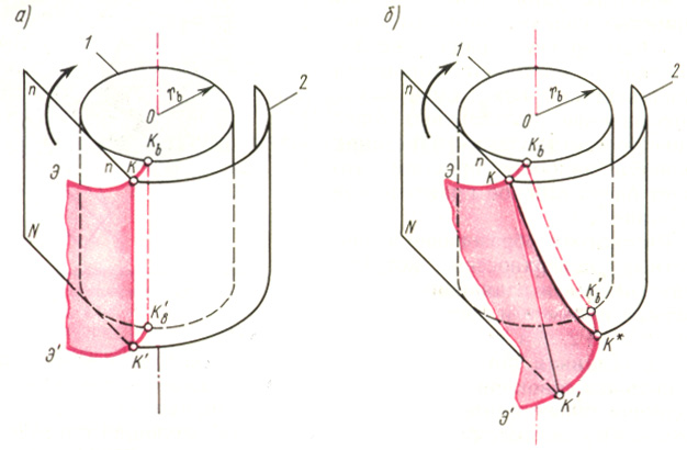
Let us consider the formation of involute surfaces, which will be the main surfaces of straight and oblique teeth. In Fig. 14.2, and in perspective the main surface of a straight tooth is shown, which can be represented as a set of completely identical involutes (E, E"), located in planes perpendicular to the axis of the wheel. These involutes are the trajectories of the points of the generatrix of the straight line QC" , belonging to the plane N , which rolls along the main cylinder 1 without sliding. The starting points of all involutes are located on the generatrix K b K b main cylinder. The intersection of the main surface of a straight tooth with any coaxial cylinder 2 occurs along the generatrix of this cylinder (for example, a straight line QC" ). This straight line is parallel to the axis of the wheel and is called the straight tooth line. The main surface of a straight tooth is an involute ruled cylindrical surface.
The main surface of an oblique tooth (Fig. 14.2, b) can also be represented as a set of identical involutes (E, E") located in planes perpendicular to the axis of the wheel; however, in this case the generatrix straight QC" located on plane N at a certain angle to the wheel axis. Due to this, when plane N rolls along the main cylinder 1 without sliding, the starting points of the involutes are located along a helical line K b K b on the main cylinder. At the intersection with any coaxial cylinder 2, the main surface of the oblique tooth forms a helix QC* , called the oblique tooth line. The main surface of an oblique tooth is an involute ruled helical surface.
Thus, the main similarity of the main surfaces of straight and oblique teeth is that in any end section, i.e. in a section by a plane perpendicular to the axis of the wheel, they have an involute.
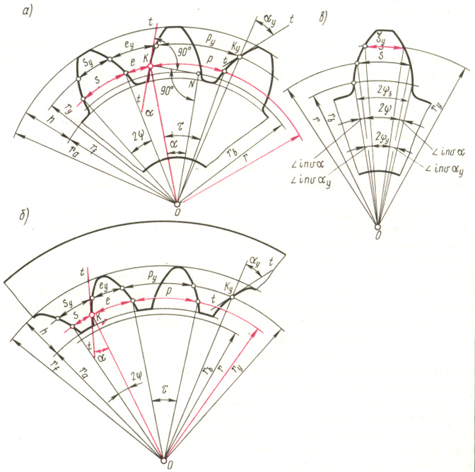
In Fig. 14.3, and shows a gear with external teeth. Largest radius r a has a circle of vertices. In Fig. 14.3. b shows a gear with internal teeth. In this case, the body of the wheel has the shape of a ring, the teeth of which face their apexes into the cavity. Therefore the radius r a the circle of the tips of the internal teeth is less than the radius r f the circumference of the depressions, which is thus the largest. In Fig. 14.3 also shows the involute tooth profile, the main circle on the basis of which it is built (radius r b ), as well as a pitch circle of radius r and a circle of arbitrary radius r y.
In Fig. 14.Z is indicated by the letter KON , equal to the angle of the tooth profile at the point K , located on the pitch circle of the spur gear. This angle is standardized and equal to 20°. Thus, the pitch circle of a spur gear is the circle that intersects the tooth profile at the point for which the profile angle is equal to the standard angle= 20°.
If the length of the circles - pitch, main and arbitrary radius - is divided by the number of teeth z , then we get the distances between the profiles of two adjacent teeth, called the pitch, i.e. we get the pitch along the pitch circle R , step along the main circle p b and step along a circle of arbitrary radius p y. Arcs p, p b and p y correspond to the same angular step = p / r = p b / r b = p y / r y . It follows that the steps are proportional to the radii of the corresponding circles. The angular step can also be expressed as follows: = 360°/ z.
An important element The wheel is pitch along the pitch circle. Let's express the length of the pitch circle in steps R and number of wheel teeth z : 2 r = pz . Hence the diameter of the pitch circle d = (p /)* z = mz . Ratio p/ denoted by a letter m and is called the wheel tooth module (module unit - mm). The module is standardized, and the standard provides whole line module values. The radius of the pitch circle and all linear dimensions of both the wheel and the gear are expressed through the module:
r = m * z /2 ; (14.1)
p = * m . (14.2)
The radius of the main circle is found from KON (Fig. 14.3, a):
(14.3)
The radius of an arbitrary wheel circumference is expressed as follows:
(14.4)
Since the steps are proportional to the radii, the step along the main circle is:
and the step along a circle of arbitrary radius:
(14.5)
The main parameters of the wheels are the module m and number of teeth z . The dimensions of the pitch circles characterize the dimensions of the wheels and gears. Since the module is determined from a strength calculation, and the number of teeth is assigned by the designer, to reduce the dimensions of the gear transmission it is necessaryreduce the number of teethits wheels [see equation (14.1]
For wheels with internal teeth, the radii of the main and pitch circles and the steps along these circles are determined by the same formulas as for a wheel with external teeth.
The pitch of the wheel teeth along any circle can be represented as the sum of the tooth thickness s y and width of the depression e y, i.e.
Wheels of the same module, having the same number of teeth, may differ from each other in tooth thickness along the pitch circle.
There are:
- wheels with equal pitch, in which the thickness of the tooth along the pitch circle is equal to the width of the cavity and, therefore, half the pitch
s = e = m/2 ;
2) wheels that s > e, i.e. s > m /2;
3) wheels that s< е , т. е. s < m /2 .
In Fig. 14.3, central angles are shown 2 and 2 y , corresponding to the arc thickness of the tooth s and s y , as well as involute angles inv and inv y . From the figure it follows:
b = + inv = y + inv y
from here
y = + inv - inv y
Expressing angular thicknesses through linear y = s y /(2 r y ) and = s /(2 r ) and substituting from the value into the equation previously compiled for y , we obtain a formula for determining the thickness of the external tooth:
s y = r y (s/r + 2inv - 2 inv y ) (14.6)
The formula for determining the thickness is prepared in a similar way s y internal tooth:
s y = r y (s/r - 2inv + 2 inv y )
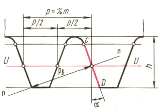
If we increase the number of wheel teeth without limit, and therefore the radii of all circles, then in the limit at z = all circles are transformed into parallel straight lines, and the involute tooth profile becomes straightforward , which is of very important practical importance. At z = we get a gear rack (Fig. 14.4). Anywhere in the straight part of the rack tooth, the profile angle will be the same, equal.
Direct UU , along which the thickness of the rack tooth is exactly equal to the width of the cavity, i.e., equal to half the pitch, is called the dividing line. The pitch of the rack teeth, measured along any straight line parallel to the pitch, has the same value p = m . Rack pitch measured normal n - n to her profile is equal mcos, i.e. equal to step p b along the main circumference of the wheel, the module of which is the same as the rack module.
Basic provisions of machine gearing.
Rack and pinion machine gearing.
Methods for manufacturing gears.Currently, gears are manufactured using copying and bending methods.
According to the first method, gears are produced mainly with only equal pitch. Moreover, most of them are carried out with a known error. The second method is the method of bending such significant shortcomings does not have: this method can produce a wide variety of gears and, moreover, theoretically accurately. Therefore, the bending method has become widespread and is of particular interest.
With the bending method, the workpiece from which the gear is made and the cutting tool having a toothed shape (hob cutter, comb, cutter) are given on the machine such movements relative to each other that reproducemeshing process. This gearing is called machine gearing.
In addition to the movements that reproduce the engagement process, the tool is also given a technological cutting movement. In this case, the cutting edges of the tool describe a surface called the producing surface. Let us point out that the producing surface and the manufactured lateral surface of the tooth are mutually enveloping, which is where the method itself gets its name.
When calculating the geometric parameters of the elements of the higher kinematic pair, the technological capabilities of manufacturing parts on shaping machines (metal-cutting, rolling mills, presses, etc.) are taken into account. The geometry of the corresponding forming tool is closely related toproducing surfaces. For tools that carry out the shaping process by cutting chips, such a producing surface is an imaginary surface containing the cutting edges of the tool or formed during their main movement necessary for cutting. If the cutting edges are straight and the main movement is linear, then the generating surface is a plane. If the cutting edges are curved, and the main movement is rectilinear, then the generating surface is a cylindrical surface (for example, an involute surface for cutters).
The engagement of the designed surface of the teeth with the producing surface, by analogy with the engagement of the wheel being cut with the producing surface of the cutting tool, is calledmachine gearing. This term was proposed by V. A. Gavrilenko, a prominent scientist who generalized and developed the basic principles of the theory of engagement of involute gears. The essence of machine gearing is that the producing surface (surface cutting edges tool) and the projected surface of the tooth (the “cut” wheel) have the same relative motion that the gears would have when engaged with each other when the axoidal surfaces interact.
When cutting cylindrical gears, the axes of the producing wheel (i.e., an imaginary gear wheel whose lateral surfaces are producing surfaces) and the designed (“cut”) wheel are parallel to each other and the axoids are cylinders. If the producing wheel has a finite number of teeth, then the cutting tools are a cutter (Fig. 14.5 f), an abrasive hone (Fig. 14.5 g), which can be used to process the side surfaces of the wheel teeth with different numbers teeth (Fig. 14.5, h). With an infinitely large radius of the axoid of the producing wheel, the tool must have an infinitely large number of teeth, i.e., turn into a rack. In this case, the tool is usually a hob cutter (Fig. 14.5, b) or an abrasive worm wheel (Fig. 14.5, d), in which the rack-and-pinion producing circuit (Fig. 14.5, e) is located on the helical surface. A special case is a tool called a gear-cutting comb (Fig. 14.5, a) or a pair of disc-shaped grinding wheels(Fig. 14.5, c). The main cutting movement for a cutter, comb and abrasive hone is translational movement, and for a hob cutter and
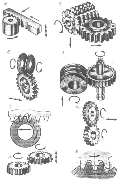
grinding wheels - rotational movement.
During the bending (rolling) movement, the main step of the tool along the profile normal corresponds to the main step of the designed (“cut”) wheel. The process of transition from the formation of one tooth to another during the rolling process is carried out automatically with continuous relative movement (Fig. 14.5, d. h).
If the generating surface is cut by a plane perpendicular to the axis of the wheel being cut, then in the section we obtain the original generating contour (IPC). Machine gearing is the engagement of the IPC with the tooth profile of the wheel being cut.
Let us consider a rack-and-pinion machine gearing, i.e. one where the IPC has the outline rack. The involute edges of this IPC are straight. Cutting tool(hob cutter or comb), which forms an involute rack IPC with its main movement, has a very valuable property: it can be manufactured relatively cheaply and accurately. The geometry of the teeth of the cut wheel is determined by the parameters of the IPC of the rack tool and its location in relation to the wheel.
Initial generating contour of an involute rack and pinion tool. The shape and dimensions of the IPC are standardized. The involute parts of the IPC tooth profile (Fig. 14.6, a) are straight and inclined to the tooth axis at an angle. Transitions from the straight part of the tooth to the base of the cavity and to the apex are made along an arc with a radius t . Interface points are marked on the IPC with letters A, C, D, E . Straight part CD is involute, and the fillets AC and DE - non-involute part of the circuit. A straight line dividing a tooth in height into two equal parts is called a dividing line. On the IPC, four more lines are marked, parallel to the dividing line and passing along the bases of the tooth cavities, along their apexes and through the mating points S and O . The distances between these straight lines express the dimensions of the tooth of the original generating contour in height and are measured accordingly by the values h a = h a * m and C = c * m, where h a * - tooth height coefficient, With * - radial clearance coefficient. According to the standard: h a * = 1.0; s * = 0.25 . Lines passing through points C and D , are called straight lines of boundary points.

The dimensions along the dividing line are pitch, tooth thickness and cavity width. Step R of the original generating circuit, measured along any straight line parallel to the dividing line, is a constant value equal to m, where m - standard module. The thickness of the tooth IPC along the dividing line is equal to the width of the cavity s 0 = e 0 = m /2 , and together they make up a step. The tooth profile angle is standardized:= 20° . Rounding radius (arc DE)
(14.7)
Thus. The IPC of a rack tool is characterized by four standard parameters: m , ha * , c * .
Rack and pinion machine gearing and displacement coefficient. Rack and pinion machine gearing, like any gearing, has initial lines. They are the machine-initial straight racks and the machine-initial circle of the wheel, which roll over each other without slipping. It can be shown that in a rack and pinion machine gearing the radius r w 0 machine starting circle is equal to the radius of the pitch circle r.
Machine rack angle w 0 equals profile angle and the original generating contour (as angles with mutually perpendicular sides). Note also that the profile angle of the wheel tooth at a point located on the pitch circle is equal to the profile angle of the original generating contour.
On the machine, the tool can be positioned differently relative to the wheel being cut. Therefore, in the machine gearing the pitch line IPC can be located in various ways in relation to the pitch circle of the wheel: I) it can touch the pitch circle - zero setting of the tool; 2) to be moved away from her positive attitude; 3) cross itnegative setting.
The distance between the dividing line and the dividing circle is calledtool offset. It is expressed as a product of the modulus m by displacement factor X and he is given a sign. At zero setting the offset m x > 0, x > 0 . With a positive setting m x > 0, x > 0. When set negatively, the offset is the segment arrow that the dividing line cuts off from the dividing circle; in this case mx< 0, x < 0.
In Fig. 14.6, a a rack-and-pinion machine gearing is depicted when cutting a gear with a positive offset and all elements of the producing initial contour, the wheel being cut and the machine gearing are indicated.
The machine rack and pinion line begins at the point N and through the pole P 0 goes to infinity. The length of its active part is limited by points B 1 and B , located at the intersection of the machine engagement line with the straight line QQ boundary points and circle of vertices (Fig. 14.6, a)
The gear tooth profile has involute and non-involute parts. The transition of an involute profile to a nonevolute one is located on the circle of the boundary points of the wheel, the radius of which is r l = OB 1 " .
The distance between the circle of the tops of the wheel teeth and the straight valleys of the IPC is the machine clearance From 0 . Its value consists of two parts: c * m, ym, where y equalization bias coefficient.
Dimensions of the manufactured gear with external teeth. Diameter of the tops of the spur gear (Fig. 14.6, a):
(14.8)
Tooth height from the same drawing:
(14.9)
If x = 0 (no tool offset) and y = 0, then d a = m (z + 2 h a *), h = m (2 h a * + c *) , and at standard values h a * = 1.0 and with * = 0.25 we get d a = m(z +2) and h = 2.25 m.
The starting line rolls along the machine starting circle (also called the dividing line) without slipping. Therefore, the tooth thickness s along the pitch circle of the wheel being cut is equal to the width MM depressions along the machine-initial straight line IPC (Fig. 14.6, b).
Segment MM consists of the width of the IPK depression along the dividing line e 0 = m /2 and two legs, each of which is equal xm tg , so:
s = m/2 + 2 xm tg (14.10)
If the tool is installed relative to the wheel without offset ( xm = 0), then s = m /2 ; means the thickness of the tooth s along the pitch circle of the wheel is equal to the width of the depression e, since s + e = m . In this case, a wheel with equal pitch is obtained s = e, If xm > 0, then s > m/2 and therefore s > e. If xm< 0, то s < m /2 , и поэтому s < e .
When cutting helical wheels, the same tool is used 1 , which is for straight teeth, but it is installed obliquely at an angle relative to the end plane t - t wheels (blanks) (Fig. 14.6, V ). This figure shows the development of index cylinder 2 of a helical gear, as a result of which the helical lines of the helical tooth are transformed into straight lines. In the end plane t - t helical gear, due to the tilt of the tool, the pitch increases and becomes equal p/cos and consequently, the module in the end plane will be non-standard, equal to m/cos . Therefore, when calculating linear dimensions helical gear according to the formulas that include the standard module, instead of m should be substituted m/cos, for example pitch diameter of helical gear d = zm/cos.
Let's pay attention to the sizes h a * m , c * m , xm , y * m , perpendicular to the dividing line (Fig. 14.6, A ), which are usually called height dimensions. In Fig. 14.6 V these dimensions are located perpendicular to the plane of the drawing. Therefore, when the tool is rotated at an angle, the height dimensions do not change. And it follows from this that when the products occur in the equations h a m , cm , xm , ym , then when calculating a helical gear, they can be substituted into these equations without any recalculation of the factors. So, for example, the formula for the diameter of the vertices of a helical gear can be written as follows: d a = d + 2(h a * m + xm - y * m ) .
The profile angle of the initial producing contour when cutting a helical gear increases compared to the standard value = 20°, since the height dimensions do not change, and the pitch in the end section increases. Design profile angle t the initial producing circuit when cutting helical wheels is determined by the formula:
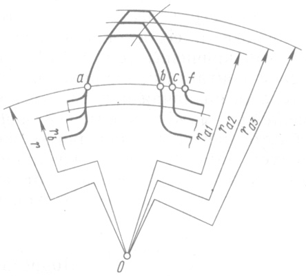
In Fig. 14.7 compares the tooth profiles of three wheels having the same number of teeth, cut with the same tool, but with different offsets: x 1< x 2 < x 3 . The wheels have the same radii of pitch and main circles; therefore, the tooth profiles of all three wheels are outlined along the same involute. But the thickness of the teeth s 1, (arc ab), s 2 (arc ac), s 3 (arc af ) and radii of vertex circles r a 1, r a 2, r a 3, the wheels will be different. As you increase X the thickness of the tooth at the base increases, and at the top it decreases, i.e., the displacement coefficient significantly affects the shape of the tooth. Consequently, by assigning one or another displacement coefficient during design, it is possible to influence the shape of the wheel teeth and the quality of the gear transmission, endowing it with the desired properties.
Control questions for the lecture N 14
- What is a gear called?
- Explain the basic elements of a gear.
- Write down the formulas for the circumferential and angular steps of an involute gear.
- What are the manufacturing methods? gear wheels You know?
- What is the essence of manufacturing involute wheels using the bending method?
- Give the definition of machine gearing.
- Derive formulas for determining the main dimensions of a gear () using a machine gearing diagram.