The mooring device is used to secure the vessel to the pier, the side of another vessel, roadside barrels, palams, as well as constrictions along the berths. The mooring device includes (Fig. 1):
- mooring ropes;
- bollards;
- mooring hawse and guide rollers;
- bale strips (with and without rollers);
- views and banquets;
- mooring mechanisms (windlasses, capstan, winches);
- auxiliary devices (stoppers, fenders, brackets, throwing ends).
Mooring ropes. Vegetable, steel and synthetic cables are used as mooring ends. The number and size of cables are determined according to the supply characteristics of a given vessel ().
 Location of mooring devices
 Plant ropes twisted from fibers plant origin. Depending on the method of weaving and diameter, they are divided into ropes, lines, pearls, cords and cables. The material of manufacture is often reflected in the name of the cable. For example, a cable made from hemp bast fibers is called hemp. Competing with hemp cables are the so-called Manila cables (Fig. 2), which are twisted from the fiber of the leaves of the spinning banana - abaca. Such cables have the advantage of low weight, but are significantly inferior to hemp cables in flexibility. Sisal (Fig. 3), coconut, cotton, jute, linen (Fig. 4) cables are also used.
Advantages and disadvantages of plant cables:
- decrease when wet;
- susceptible to mold development;
- With use, the strength of plant cables quickly decreases.
 Rice. 2 Manila cable
  Rice. 3 Sisal cable
  Rice. 4 Lianoy cable
 Synthetic ropes have great benefits before plants. They are much stronger and lighter, more flexible and elastic, moisture-resistant, do not lose strength when wet and are not subject to rotting, and are resistant to solvents. Synthetic ropes are very elastic. At a load equal to half the breaking force, the relative elongation of braided eight-strand ropes reaches up to 35-40%, without losing strength.
Synthetic cables made from polymer materials. Depending on the brand of polymer, they are divided into polyamide, polyester and polypropylene.
Polyamide ropes(Fig. 5) are distinguished by their ability to absorb impact energy, they have excellent strength and very good wear resistance.
Polyester(polyester) cables (Fig. 6) are made from fibers of Lavsan, Lanon, Dacron, Dolen, Terylene, and other polymers. Characterized by excellent resistance to climatic conditions, very good strength and wear resistance. Unlike polyamide ropes, they are flexible and soft even when wet. Polyester ropes are very suitable as mooring ropes and ropes for lifting heavy loads.
Polypropylene rope(Fig. 7) has average wear resistance and good strength. In the production of polypropylene ropes, film fibrillated thread or multifilament fiber is used, which themselves have excellent mechanical properties and high reliability. In the latter case, the rope turns out to be smoother and more pleasant to the touch. It has high resistance to bending, increased resistance to chemically active environments, high strength and at the same time is not hygroscopic, and therefore does not lose its properties when immersed in water. Such products are not subject to the destructive effects of fungi and bacteria, and therefore do not rot even after prolonged use in an environment with high humidity. Polypropylene ropes have high elasticity, which makes it possible to create various products with a fixed shape from them. Polypropylene mooring lines are especially convenient when sailing over long distances, as they float.
Synthetic fibers are easily distinguished by the following characteristics:
- if the sample does not sink in water, then it is made of polyethylene; if it sinks, then it is either polyamide or polyester;
- if during combustion there is dark smoke and the sample melts, then it is polyester; if it melts without changing color, then it is polyamide, polypropene or polyethylene;
- if the sample is moistened with 90% phenol or 85% formic acid (a few drops on a piece of glass) and the fiber dissolves, then it is polyamide; if the sample does not dissolve, it is polyester;
- if it does not dissolve and remains flexible - polypropene or polyethylene.
 Rice. 5 Polyamide rope
  Rice. 6 Polyester rope
  Rice. 7 Polypropylene rope
 Currently, composite and combined synthetic ropes using various types fibers and threads.
It is not allowed to use synthetic cables that have not undergone antistatic treatment and do not have the appropriate certificates.
Steel cables They are used less and less often, since they do not withstand dynamic loads well and require great physical effort when transferred from the ship to the pier. The most common on sea vessels are steel mooring lines with a diameter of 19 to 28 mm. Cables are lubricated (tired) at least once every three months and each time after the cable is in water.
To ensure timely detection of defects, mooring lines must be thoroughly inspected once every six months. Inspection must also be carried out after anchoring on mooring lines in extreme conditions.
At one end of the mooring rope there is a loop - a light, which is put on the shore bollard or fastened with a bracket to the eye of the mooring barrel. The other end of the cable is secured to bollards installed on the deck of the ship.
They are paired cast iron or steel cabinets, located at some distance from each other, but having a common base (Fig. 8). In addition to ordinary bollards, in some cases, especially on low-sided ships, cross bollards are used, which can be either double or single.
 Rice. 8 Bollards: 1 - base; 2 - cabinet; 3 - cap; 4 - tide; 5 - stopper; 6 - butt
  Rice. 9 Fastening the mooring rope to the bollard
 Mooring cables on bollards are secured by placing a number of hoses in the form of a figure eight so that the running end of the cable is on top (Fig. 9). Usually two or three full eights are applied and only in exceptional cases the number of hoses is increased to 10. To prevent the cable from self-resetting, a grip is placed on it. To secure each mooring line brought ashore, there must be a separate bollard.
To pass mooring lines from the ship to the shore, a mooring hawse is made in the bulwark - a round or oval hole bordered by a cast frame with smooth rounded edges (Fig. 10). Currently, universal fairleads with a rotary cage and rollers are increasingly used (Fig. 11). Such fairleads protect the cable from chafing.
 Rice. 10 Mooring hawse
  Rice. 11 Universal fairlead
 In those places where there is no bulwark, instead of mooring fairleads, bale strips are installed to protect the cable from chafing and give it the necessary direction (Fig. 12). There are several types of bale strips. Bales without rollers are usually used only on small ships with a small diameter mooring cable. Rollers reduce wear on cables and reduce the effort required to pull them out. In addition to bale strips, guide rollers are also used to change the direction of the cable, which are located on the deck near the mooring mechanisms (Fig. 13).
 Rice. 12 Bale strips: a) - with three rollers; b) - with two rollers; c) - without rollers
  Rice. 13 Guide rollers
 Views and banquets. Views and banquets are used to store mooring ropes (Fig. 14, 15). The latter are a horizontal drum, the shaft of which is fixed in the bearings of the frame. The drum has discs on the sides that prevent the cable from coming off.
 Rice. 14 Storing the cable on the views
  Rice. 15 Cable storage on banquets
 Throwing ends (throwouts) and fenders. Parts of the mooring device also include throwing ends and fenders. The throwing end is made from a line about 25 m long. At one end there is a piebald - a canvas bag filled with sand (Fig. 16).
 Rice. 16 Prepared for mooring workplace: 1 - cable; 2 - ejection; 3 - portable chain stopper
 Fenders are used to protect the ship's hull from damage during mooring. Soft fenders are most often made from braided old plant rope. Cork fenders are also used, which are a small spherical bag filled with small cork. Recently, pneumatic fenders have been increasingly used.
Mooring mechanisms. Spikes, mooring simple and automatic winches, and windlasses (for working with bow mooring lines) are used as mooring mechanisms for selecting and tightening mooring lines. Mooring capstans are installed to work with stern mooring lines. They take up little space on the deck; the capstan drive is located below the deck (Fig. 17).
 Rice. 17 Mooring capstan
 On the forecastle, windlass mooring turrets are used to remove mooring ropes (Fig. 18). Automatic mooring winches can be installed to work with stern and bow moorings (Fig. 19). The mooring line is permanently located on the winch drum; it is not required preliminary preparation before feeding and transferring to bollards after tightening. An automatic winch independently unwinds the moorings when it is over-tensioned or picks it up if the moorings have become slack.
 Rice. 18 Using the windlass head
  Rice. 19 Automatic winches
 The mooring cable selected using the mechanism is transferred to the bollards and secured. To prevent it from being etched when moving the cable, a stopper is first placed on it (Fig. 20).
 Rice. 20 Portable stoppers: a) - chain; b) - vegetable; c) - synthetic
 The stopper is attached to the eye at the base of the bollard or to the butt on the deck of the ship (Fig. 21). When working with steel mooring lines, you should use chain stoppers with a chain length of at least 2 m, a caliber of 10 mm and a plant cable at least 1.5 m long at the running end (Fig. 22). The use of chain stoppers for vegetable and synthetic cables is unacceptable.
 Rice. 21. Attaching the portable stopper to the bollard
  Rice. 22 Holding the mooring rope with a stopper
 The stopper is pulled along the mooring line in the direction of tension. When the mooring line is secured to the stopper, you should not abruptly release the cable from the capstan or capstan, so as not to jerk the stopper off. The mooring lines should first be carefully set by moving the capstan or windlass in reverse, without removing the hoses from the drum, and only after making sure that the stopper securely holds the mooring lines, quickly transfer the latter to the bollard.
On larger vessels, stationary stops can be used, which are installed on the deck between the hawse or bale strip and the bollard. Selecting and securing mooring ropes is greatly simplified when using bollards with rotating bollards. The mooring lines are placed in figure eights on the bollard bollard and fed to the windlass head. When the cable is pulled out, the bollard bollards rotate, allowing the cable to pass freely. After removing the cable from the windlass head, it will not be pulled out, since the bollards have a stopper that prevents them from turning in the opposite direction.
Suggested reading:
The mooring device is intended for attaching a vessel to a pier, mooring barrels and beams, or to the side of another vessel.
The device includes:
Mooring ropes;
Bale strips;
Guide rollers;
Mooring mechanisms.
Accessories:
Stoppers;
Throwing ends;
Mooring ropes (mooring lines, mooring lines) There are steel, vegetable and synthetic.
Mooring ropes (ropes ). They are used as mooring lines vegetable, steel and synthetic cables . Steel cables are used less and less often, since they do not take dynamic loads well and require great physical effort when transferred from the ship to the pier. The most common on sea vessels are steel mooring lines with a diameter of 19 to 28 mm.
Service life of ship cables:
Steel cables – running rigging from 2 to 4 years ;
Vegetable and synthetic ropes - cable work - 3 years , Perline – 2 years ;
- other cables – 1 year.
The ends of the mooring ropes end in a loop called - fire.
Number mooring ropes on the ship, their length and thickness determined by the Register Rules .
Establishment layout mooring lines shown on rice.

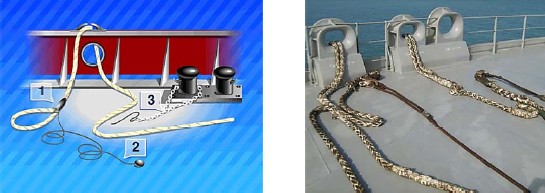
Main mooring lines served from the bow and stern ends of the vessel in directions excluding the movement of the vessel along the berth and departure from it . IN depending on the direction mooring lines got their names . Moorings wound up from the bow and stern ends of the vessel , holding vessel from movement along the pier are called bow (1) and stern (2) longitudinal. Mooring line, whose direction opposite to longitudinal called spring. Nasal (3) and stern (4)springs are used for the same purposes as longitudinal ends. Moorings, wound up perpendicular to the pier , are called nasal (5) And stern (6) clamping. The clamping ends prevent the vessel from moving away from the berth in a strong wind.
Bollards – cast or welded bollards (steel and cast iron) for fastening mooring cables. On transport ships usually paired bollards with two pedestals are installed on a common base, having hot flashes to hold the lower cable hoses, and hats does not allow the upper ropes of the mooring line to jump off the bollards.

Bollards are also installed with cabinets without tides,
and bollards with cross .
Bollards with cross convenient for mounting mooring lines , aimed from above at an angle to the deck . Similar bollards install in the bow and stern parts of the vessel both sides symmetrically .
Sometimes on ships they install one pedestal bollards – bitengi , which are used for towing .
Bitengi- represent massive cabinets , the bases of which are attached to upper deck or passed through it and attached to one of the lower decks . To hold the cable on the bits there are spreaders .
Convenient when performing mooring operations – bollards with rotating pedestals, equipped with a locking device.
Pinned to berth moorings put "eight" two or three hoses on the bollard bollards, and then on Turkish girl windlass. When cable is selected , cabinets rotate and pass the cable freely . When the cable is selected, the bollards rotate and pass the cable freely. At the right moment, remove the cable from little Turks and apply and apply additional hoses to the bollard bollards. At the same time, the stopper keeps the cabinets from rotating.
Cluses – devices through which mooring lines are passed from a vessel. Cluses are steel (cast iron) with holes round shape ,

or oval shape , bordering the holes in ship's bulwark .
Working surface hawse has smooth curves , excluding sharp bends of mooring lines .
For mooring to on board small-size floating craft, use fairleads with tides - horns.
In places where instead bulwark made railing , special fairleads are fixed on the deck at the edge of the side.
Strong mooring line friction about the working surfaces of the fairleads of these structures leads to rapid wear of cables , especially synthetic ones, so they are widely used on ships universal fairleads ,
And rotary universal fairleads.

A universal hawse has vertical and horizontal rollers freely rotating in bearings, forming a gap into which the cable fed to the shore is passed. Rotating one of the rollers when pulling the cable from any direction significantly reduces friction. The rotary universal hawse has a rotating ball-bearing cage in the body.
Bale strips have the same purpose as mooring hawse .
By design, bale strips are simple ,

with biting ,

with one roller ,

with two rollers ,

with three – Rolls.

For guiding mooring lines supplied to high berths and ships with high sides, use closed bale strips.
The most widespread bales with rollers , the use of which is significant reduces the effort required to overcome the frictional forces that arise when pulling out the cable .
To route mooring cables from the hawse to the mooring mechanism drums, metal bollards with guide rollers.

Views – designed for storing mooring ropes. They have locking devices . Install them in bow and stern parts of the ship not too much far from the bollards .

Mooring mechanisms– serve to pull a vessel with mooring lines in place to the pier, the side of another vessel, a barrel, to pull the vessel along the pier, as well as automatic regulation tension of mooring lines when the water level fluctuates, tidal water currents, changes in draft during loading or unloading of the vessel.
Mooring mechanisms include:
- windlass;
- mooring spiers;
- anchor mooring winches;
- simple and automatic winches.
Windlasses and mooring capstans, have drums (turrets) that are used to pull out mooring ropes .

On ships that do not have stern anchor device , installed at the stern of the vessel mooring capstans that do not have a chain drum.

Vertical location of the axis of rotation of the capstan mooring drum allows select moorings from any direction . Concave external the surface of the capstan drum and windlass can be smooth or have vertical welps - rounded ribs .
Welps– prevent the cable from sliding on the drum. However, due to kinks on them cause mooring ropes to be damaged more quickly . Therefore, with widespread use on ships synthetic ropes subject to greater friction when working on a capstan, capstan drums make smooth .
Anchor mooring winches, installed on some ships instead windlasses , and are used during mooring operations in the same way as windlasses.

Simple mooring winch It has electric motor with built-in disc brake . The rotation of the winch engine is transmitted through mechanisms inside to the shaft with the mooring drum. Through work disc brake, you can adjust the speed of rotation of the mooring drum.

Automatic mooring winch differs favorably from a simple winch in that it can work in manual and automatic mode . IN manual mode the winch is used for pulling the ship to the pier and for selecting the given cables. After the cable is pulled tight, it remains on the winch drum . winch switch to automatic mode , setting required cable tension force . At change, for any reason, in the tension force of the cable, the winch automatically picks up or releases the mooring cable, ensuring constant tension of the mooring cable .

Automatic winches are manufactured in two versions:
- with mooring turret , connected to the mooring drum by a release coupling;
- without the turret , which are installed near the windlass and capstan.
Stoppers serve to hold mooring ropes in in a tense state when transferring them from the mooring mechanism drum to the bollards.
There are stoppers: chain (Fig. a), vegetable or synthetic (Fig. b).

Chain stopper represents rigging chain diameter 10 mm , And length 2 – 4 m , with a long link for fastening with a bracket to the deck butt, at the other end of the stopper there is a vegetable or synthetic cable at least 1.5 m long . And thick V twice as thin than the mooring end.
Stopper from vegetable or synthetic rope made from the same material as mooring ropes only twice as thin.
Throwing end necessary for supplying the mooring cable to the shore when the vessel approaches the pier.

Throwing end- This vegetable or synthetic tench thick 25 mm , length – 30 – 40 m , on one side of which is tied lightness (a weight braided with a thin plant torso) for increasing throwing distance , the other end is tied to the mooring line light .
Fenders.
Fenders – intended for protection of the ship's hull from impacts on the quay wall , or about on board another ship during mooring operations and vessel anchorage.

Fenders there are soft And hard
Soft fenders- This bags filled tightly with elastic material And braided with strands of plant rope or packed in special cases . Soft fenders have a fender with a thimble for attaching a vegetable or synthetic cable to it, the length of which should be sufficient overboard at low berths and the smallest draft.
Hard fenders – wooden blocks, suspended on cables from the side of the ship. To give such a fender elasticity, it is braided along its entire length with vegetable or synthetic cable.
Steering device of the ship.
Steering gear- serves for ship control . With steering device you can change the direction of the ship's movement or keep it on a given course . During To keep the ship on a given course, the task of the steering device is to counteract external forces:
Currents that can cause the ship to deviate from its intended course .
Steering devices have been known since the appearance of the first floating craft. In ancient times, steering devices were large swinging oars mounted at the stern, on one or both sides of the ship. During the Middle Ages, they began to be replaced with an articulated rudder, which was placed on the sternpost in the center plane of the ship. It has been preserved in this form to this day.
The steering device consists of the following parts:
- Steering wheel allows you to keep the ship on a given course and change the direction of its movement. It consists of a steel flat or streamlined hollow structure - rudder , and the vertical rotary shaft – ballera , rigidly connected to the rudder blade. To the top end ballera brought out onto one of the decks sector planted or lever - tiller, to which an external force is applied to turn baller .
- Steering motor the stock rotates through the drive, which ensures rudder shifting. Engines are steam, electric and electro-hydraulic. The engine is installed in the tiller compartment of the vessel.
- Control station serves for remote control steering motor. It is installed in the wheelhouse. The controls are usually mounted on the same column as the autopilot. To control the position of the rudder blade relative to the center plane of the vessel, indicators are used - axiometers.

Depending on the principle of operation, they are distinguished:
Passive steering wheels;
Active steering wheels.
Passive They are called steering devices that allow the vessel to turn only while underway, while the water is moving relative to the hull of the vessel.
Unlike him active The rudder allows you to turn the vessel regardless of whether it is moving or stationary.
Based on the position of the rudder blade relative to the axis of rotation of the stock, the following are distinguished:
- simple steering wheel – the plane of the rudder blade is located behind the axis of rotation of the propeller ;

- semi-balanced steering wheel– only a large part of the rudder blade is located behind the axis of rotation of the propeller, due to which a reduced torque occurs when the rudder is shifted;
- balance steering wheel– the rudder blade is located on both sides of the rotation axis so that no moments arise when shifting the rudder.
Active steering device– an electric motor is built into the rudder blade, driving the propeller into rotation. The electric motor is placed in the nozzle to protect it from damage. By turning the rudder blade together with propeller At a certain angle, a transverse stop appears, making it easier to turn the vessel. The active rudder also performs its functions while the vessel is at anchor. Active rudders are usually installed on special vessels where high maneuverability is required.

To facilitate the maneuverability of the vessel during mooring operations, bow and stern thrusters are used. Thrusters are distinguished:
- thrusters With counter-rotating screws.

- thruster with reverse rotation of the propeller.
In order for the active steering device to operate, the passive rudder blade must be at a certain angle. The rudder stock is driven into rotation by a steering gear installed below the deck at the stern of the vessel..
Operating principle electric steering device.

1 manual steering wheel drive (emergency drive);
2 tiller;
3 gearbox;
4 steering sector;
5 electric motor;
6 spring;
7 rudder stock;
8 rudder feather;
9 segment worm wheel and brake;
10 worm.
If it is needed turn the rudder , need to run, electric motor with a certain rotation speed which is associated with steering column on the navigation bridge . Through electrical devices (selsyns, rotating transformers ) torque from the helm steering column on the navigation bridge transmitted to electric motor of the steering device and from it to the rudder blade.
At Electric steering malfunction the steering wheel is driven to movement using a manually controlled mechanism consisting of a manual steering wheel . By turning helm through worm gear rotation is transmitted to tiller and from him to rudder stock .
On modern ships use a steering device with an electro-hydraulic motor .

1 connector for connecting to the ship's electrical network;
2 ship cable connections;
3 spare canister with hydraulic fluid;
4 steering pump;
5 steering column with telemotor sensor;
6 indicator device;
7 telemotor receiver;
8 engine;
9 hydraulic steering machine;
10 rudder stock;
11 steering indicator sensor.
When the steering wheel on the steering column in the wheelhouse rotates, the transmitting and receiving telemotor sensor on the steering column and steering gear is triggered. Flowing under pressure into in the pipeline, the liquid moves the rod in the telemotor receiver, which transmits movement to the steering pump in the appropriate direction . From the steering pump, the movement is transmitted to the steering stock.
CONTROL AND MANEUVERING OF THE SHIP DURING MOORING OPERATIONS
COMPOSITION OF MOORING DEVICE
The mooring device is used to secure the vessel to the pier, the side of another vessel, roadside barrels, palams, as well as to tighten the piers of the berths. The mooring device includes:
Mooring ropes;
Mooring hawse and guide rollers;
Bale strips (with and without rollers);
Views and banquets;
Mooring mechanisms (windlasses, capstan, winches);
Auxiliary devices (stoppers, fenders, brackets, throwing ends).
Mooring ropes
Vegetable, steel and synthetic cables are used as mooring ends.
The number and size of cables are determined according to the supply characteristics of a given vessel.
Steel cables are used less and less often, since they do not take dynamic loads well and require great physical effort when transferred from the ship to the pier. The most common on sea vessels are steel mooring lines with a diameter of 19 to 28 mm. The use of steel cables on oil tankers is prohibited.
Mooring lines made from synthetic cables are widely used. They are lighter than steel and vegetable moorings of equal strength, have good flexibility, which is maintained at relatively low temperatures.
The most convenient mooring lines are made of polypropylene or terylene ropes. They are inferior in strength to nylon ones, but due to less elasticity they better fix the position of the vessel at the berth and are less dangerous when using mooring mechanisms. Polypropylene moorings are especially convenient when sailing over long distances, as they float. At the same time, they have little resistance to abrasion and melt during friction. It is not allowed to use synthetic cables that have not undergone antistatic treatment and do not have certificates.
To use positive traits synthetic ropes various types Combined synthetic cables are produced. On mooring winches, where the mooring lines are steel, the part that goes to the shore is made of synthetic cable in the form of a so-called “spring”.
Rice. 1. Mooring winch
To ensure timely detection of defects, mooring lines must be thoroughly inspected at least once every 6 months. Inspection must also be carried out after mooring in extreme conditions.
Rice. 2. Mooring of the vessel on mooring lines
There is a loop at one end of the mooring rope - fire, which is put on the shore pedestal or secured with a bracket to the eye of the mooring barrel. The other end of the cable is secured to bollards installed on the deck of the ship.
Bollards
Bollards are paired cast iron or steel bollards located at some distance from each other, but having a common base. In addition to ordinary bollards, in some cases, especially on low-sided ships, cross bollards are used, which can be either double or single.
Rice. 3. Bollards: 1 – base; 2 – cabinet; 3 – cap; 4 – tide;
5 – stopper; 6 - butt
Mooring cables on bollards are secured by placing a number of hoses in the form of a figure eight so that the running end of the cable is on top. Usually two or three full eights are applied and only in exceptional cases the number of hoses is increased to 10. To prevent the cable from self-resetting, a grip is placed on it. To secure each mooring line brought ashore, there must be a separate bollard.
Rice. 4. Fastening the mooring rope to the bollard
Cluses
To pass mooring lines from the ship to the shore, a mooring hawse is made in the bulwark - a round or oval hole bordered by a cast frame with smooth rounded edges. Currently, they are increasingly used universal fairleads, having a rotating holder and a roller. Such fairleads protect the cable from chafing.
Rice. 5. Common hawse
Rice. 6. Universal hawse
Bale strips
A mooring device is designed to secure a vessel to a berth, mooring barrels and beams, or to the side of another vessel. The device includes mooring ropes, bollards, fairleads, bale strips, guide rollers, views, mooring mechanisms, as well as auxiliary devices - stoppers, throwing ends, fenders, mooring shackles.
Mooring ropes (mooring lines) can be steel, vegetable and synthetic. The number of mooring ropes on the ship, their length and thickness are determined by the Register Rules.
The main mooring ropes (Fig. 1) are supplied from the bow and stern ends of the vessel in certain directions, preventing the vessel from moving along the berth and moving away from it. Depending on these directions, mooring lines got their names. Cables supplied from the bow and stern ends keep the ship from moving along the pier and are called bow, respectively. 1 and stern 2 longitudinal. A cable whose direction is opposite to its longitudinal end is called spring. Nasal 3 and stern 4 springs are used for the same purposes as longitudinal ones. Cables placed in a direction perpendicular to the pier are called bow 5 and stern 6 clamps. They prevent the ship from leaving the berth in strong winds.
Rice. 1. Mooring ropes.
Cast or welded bollards (steel and cast iron) for fastening mooring ropes. On transport ships, paired bollards are usually installed with two bollards on a common base, which have bosses to hold the lower rope hoses, and caps that do not allow the upper hoses to jump off the bollards (Fig. 2, A). Bollards with pedestals without tides are also installed (Fig. 2, b) and bollards with a cross (Fig. 2, V). The latter are convenient for attaching mooring cables directed from above at an angle to the deck. Bollards are installed in the bow and stern parts of the vessel, as well as on the upper deck on both sides symmetrically.

Rice. 2. Bollards.
Sometimes single-bollard bollards - bitings - are installed on transport ships (Fig. 2, G), which are used when towing. Bitens are massive bollards, the bases of which are attached to the upper deck or passed through it and attached to one of the lower decks. To better hold the cable on the bits there are spreaders.
Bollards with bollards that rotate in bearings and are equipped with a locking device are very convenient for performing mooring operations (Fig. 2, d). The mooring line fixed to the pier is placed in a figure of eight with two or three ropes on the bollard bollards, and then on the windlass head. When the cable is selected, the bollards rotate and pass the cable freely. At the right moment, remove the cable from the turret and place additional hoses on the bollard bollards. At the same time, the locking device keeps the cabinets from rotating.
devices through which mooring lines are passed from a vessel. They are steel (cast iron) castings with round holes (Fig. 3, A) or oval (Fig. 3, b) shapes bordering the same holes in the bulwark of the ship. The working surface of the fairleads has smooth curves, eliminating sharp bends of the mooring cables. For mooring small floating craft to the side of the ship, fairleads with tides - horns are used (Fig. 3, V). For the same purpose, in the immediate vicinity of the fairleads, cleats are welded to the bulwark or to its posts. In places where railings are made instead of a bulwark, special fairleads are fixed on the deck at the edge of the side (Fig. 3, G). To supply mooring lines, towing fairleads, firmly attached to the bow visor and stern of the vessel, are used, primarily intended for inserting towing ropes.

Rice. 3. Fairleads.
Strong friction of mooring lines on the working surfaces of hawses of these structures leads to rapid wear of cables, especially synthetic ones, which is why universal ones are widely used on ships (Fig. 3, d) and rotary universal (Fig. 3, e) hawse. A universal hawse has vertical and horizontal rollers rotating freely in bearings, forming a gap into which the cable fed to the shore is passed. Rotating one of the rollers when pulling the cable from any direction significantly reduces friction. The rotary universal hawse has a cage rotating on ball bearings in the body.
have the same purpose as mooring fairleads. They are simple in design (Fig. 4, A), with biting (Fig. 4, b), with one (Fig. 4, V) or several - two (Fig. 4, G), three (Fig. 4, d) - Rolls. To guide mooring lines supplied to high berths and ships with high sides, closed bale strips are used (Fig. 4, e). The most widely used are bale strips with rollers, the use of which significantly reduces the effort required to overcome the friction forces that arise during rope removal.

Rice. 4. Bale strips.
To route mooring ropes from the hawse to the mooring mechanism drums, metal bollards with guide rollers are installed on the forecastle and poop decks .
Views designed for storing mooring ropes. They have locking devices. They are installed in the bow and stern of the vessel, not too far from the bollards.
Mooring mechanisms serve to pull a vessel with mooring lines in place to the pier, the side of another vessel, a mooring barrel, to pull the vessel along the berth, as well as to automatically regulate the tension of mooring cables when the water level fluctuates due to tidal phenomena or when the vessel's draft changes during cargo operations.
Ship mooring mechanisms are: windlass, anchor-mooring and mooring capstans, anchor-mooring winches, simple and automatic mooring winches.
Windlasses and anchor-mooring capstans have drums (turrets) that are used for pulling out mooring cables. On ships that do not have a stern anchor device, a mooring capstan that does not have a chain drum is installed at the stern. The vertical location of the axis of rotation of the capstan mooring drum allows you to select moorings from any direction. The concave outer surface of the drum can be smooth or have vertical welps - rounded ribs. Welps prevent the cable from sliding along the drum, however, due to kinks on them, the cable is damaged more quickly. Therefore, when synthetic cables are widely used on ships, subject to a lot of abrasion on rough surfaces, it is preferable to have capstans with smooth drums.
Anchor-mooring winches, installed on some ships instead of windlasses, are used in mooring operations in the same way as windlasses.

Rice. 5. Diagram of a simple mooring winch.
A simple mooring winch (Fig. 5) has an electric motor 1 with built-in disc brake. Rotation of the motor through a worm gearbox 2 transmitted to the intermediate shaft on which the gear is mounted 3 open cylindrical gear and friction clutch 4. Through a large gear, rotation is transmitted to the working shaft with the mooring drum 9. A band brake is mounted on the drum disk 5 With manual drive. Switching the friction clutch on and off is done manually 6. Mooring rope 8 laid on the drum in even rows using a cable laying machine 7 .
An automatic mooring winch (Fig. 6) differs favorably from a simple one in that it can operate in manual and automatic modes. In manual mode, the winch is used to pull the vessel to the pier and to retrieve the released cables. After the mooring rope is pulled tight when pulling the vessel, it remains on the drum, and the winch is switched to automatic mode, for which the required mooring tension force is automatically set. If for any reason the load on the cable deviates from the set one, the winch automatically picks up or releases the mooring cable, ensuring a constantly specified tension.

Rice. 6. Diagram of an automatic mooring winch.
The length of the mooring cable that can be automatically released by the winch when the load exceeds the set one is limited. In this case, they proceed from the greatest possible changes in the position of the vessel relative to the berth. If, for example, during a strong squeezing wind, the cable tension exceeds the set value on the machine, then the winch releases the specified length of the cable, after which the machine will clamp the drum with the brake and a light or sound signal will turn on on the winch, indicating an emergency mode of its operation. When choosing a limit for the permissible length of the mooring rope to be released, it is recommended to set the alarm in such a way that the signal turns on at the moment when the full first row of the rope remains on the drum. This installation will give time to eliminate the danger of completely releasing the mooring line.
Automatic winches are manufactured in two versions: with a mooring turret connected to the mooring drum by a release coupling, and without a turret. The latter are installed near the windlass and capstan.
Stoppers serve to hold mooring ropes when transferring them from the mooring mechanism drum to the bollards. They are chain, vegetable and synthetic. The chain stopper is a piece of rigging chain with a diameter of 10 mm, a length of 2-4 m, with a long link for fastening with a bracket to the deck butt at one end and a plant cable at least 1.5 m long at the other. The stopper for vegetable and synthetic cables is made of the same material as the cable, but half as thick.
Throwing ends are necessary for feeding mooring ropes to the shore when the ship approaches the pier. The throwing end is a plant line or a braided nylon cord 25 mm thick, 30-40 m long, with small fires embedded at the ends. One of them is used for attaching lightness - a small canvas bag tightly filled with sand and braided with skimushgar, the other - for the convenience of using the throwing end.
Fenders are designed to protect the ship's hull from damage when moored, parked at a pier or on board another ship. They are soft and hard.
Soft fenders are canvas bags tightly stuffed with elastic, non-deformable material (for example, cork chips) and braided with strands of plant rope. The fender has a fire with a thimble for attaching a plant cable to it, the length of which should be sufficient to fasten the fender overboard at low berths and the smallest draft.
Rigid fenders are wooden blocks suspended on cables from the side of the vessel. To give such a fender elasticity, it is braided along its entire length with an old plant cable.
Mooring shackles used for fastening the mooring rope to the shore eye or the eye of the mooring barrel.
Each vessel must have a mooring device that ensures that the vessel is pulled to shore or floating berth structures and that the vessel is securely fastened to them. The mooring device is used to secure the vessel to the pier, the side of another vessel, roadside barrels, palams, as well as constrictions along the berths. The mooring device includes (Fig. 6.32):
- mooring ropes (Fig. 6.33);
- bollards;
- mooring hawse and guide rollers;
- bale strips (with and without rollers);
- views and banquets;
- mooring mechanisms (windlasses, capstan, winches);
- auxiliary devices (stoppers, fenders, brackets, throwing ends).
Fig.6.32. Mooring device

Rice. 6.33. Names of mooring lines
Mooring lines (ropes). Vegetable, steel and synthetic cables are used as mooring ends.
Steel cables are used less and less often, since they do not take dynamic loads well and require great physical effort when transferred from the ship to the pier. The most common on sea vessels are steel mooring lines with a diameter of 19 to 28 mm. The steel mooring lines are stored on hand lines equipped with a brake pressed by a pedal to the cheek of the drum. On large-tonnage vessels, mooring eyes with a drive are installed.
Mooring lines made from synthetic cables are widely used. They are lighter than steel and vegetable moorings of equal strength, and have good flexibility, which is maintained at relatively low temperatures. It is not allowed to use synthetic cables that have not undergone antistatic treatment and do not have certificates.
To use the positive qualities of various types of synthetic cables, combined synthetic cables are produced. On mooring winches, where the mooring lines are steel, the part that goes to the shore is made of synthetic cable in the form of a so-called “spring”.
On ships transporting flammable liquids in bulk with a vapor flash point below 60°C, the use of steel cables is permitted only on decks of superstructures that are not the top of cargo bulk compartments, unless pipelines for receiving and discharging cargo pass through these decks. Cables made of artificial fiber may be used on tankers only with special permission from the Register (sparks may be generated when these cables break).
To ensure timely detection of defects, mooring lines must be thoroughly inspected at least once every 6 months. Inspection must also be carried out after mooring in extreme conditions.

Rice. 6.34. Scheme for installing mooring lines on the side facing the berth:
nasal: 1 – longitudinal; 2 – clamping; 3 – spring;
stern: 4 - spring; 5 – clamping; 6 – longitudinal
Depending on the position relative to the vessel, mooring lines are called: longitudinal, clamping, springs (bow and stern, respectively) (Fig. 6.34). The mooring lines at the outboard end have a loop - a light, which is thrown over the shore pole or fastened with a bracket to the eye of the mooring barrel (Fig. 6.35). The other end of the cable is secured to bollards installed on the deck of the ship.

Rice. 6.35. Mooring line fastening on the shore bollard
Bollards are paired cast iron or steel bollards located at some distance from each other, but having a common base (Fig. 6.36). In addition to ordinary bollards, in some cases, especially on low-sided ships, cross bollards are used, which can be either double or single.

Rice. 6.36. Bollards:
1 - base; 2 - cabinet; 3 - cap; 4 - tide; 5 - stopper; 6 - butt
Mooring cables on bollards are secured by placing a number of hoses in the form of a figure eight so that the running end of the cable is on top (Fig. 6.37). Usually two or three full eights are applied and only in exceptional cases the number of hoses is increased to 10. To prevent the cable from self-resetting, a grip is placed on it. To secure each mooring line brought ashore, there must be a separate bollard.

Rice. 6.37. Fastening the mooring rope to the bollard
To pass mooring lines from the ship to the shore, a mooring fairlead is made in the bulwark - a round or oval hole bordered by a cast frame with smooth rounded edges (Fig. 6.38).

Rice. 6.38. Cluses
To guide mooring lines from automatic winches, universal rotary fairleads are usually installed (Fig. 6.39). Such fairleads protect the cable from chafing. On ships traveling through the Panama Canal, where the vessel is navigated through the locks using shore tractors, Panama hawsees must be installed, which have a larger radius of curvature of the working surface than that of the onboard canal, and are better suited for working with large-diameter moorings.

Rice. 6.39. Universal hawse
Bale strips are designed to change the direction of the mooring line (Fig. 6.40). On most modern ships, bale strips are installed from two or three separate rollers. Bales without rollers are usually used only on small ships with a small diameter mooring cable.

Rice. 6.40. Bale strips:
a) – with three rollers; b) – with two rollers; c) – without rollers
Rollers reduce wear on cables and reduce the effort required to pull them out. Deflection (deck) rollers are installed near the mooring mechanism, which prevents the mooring line from skewing on the drum (turret) (Fig. 6.41).

Rice. 6.41. Rolls
Views and banquets. Banquets and views are used to store mooring ropes (Fig. 6.42, 6.43). The latter are a horizontal drum, the shaft of which is fixed in the bearings of the frame. The drum has discs on the sides that prevent the cable from coming off.

Rice. 6.42. View

Rice. 6.43. Banquet rope
Throwing ends (throwouts). To supply moorings to the shore or other structure, a throwing end is usually used - a light hemp cable with sand in a cable braid at the end (Fig. 6.44).

Rice. 6.44. Throwing end
The end is attached to the mooring line and the latter is fed through the mooring or towing fairlead (Fig. 6.45). The discharge is placed in the slings and, holding the free end, is thrown onto the pier. With the help of this light cable, relatively heavy mooring lines are pulled ashore. The throwing end is made from a line about 25 meters long.
Rice. 6.45. Workplace prepared for mooring:
1 - cable; 2 - ejection; 3 - portable chain stopper
Fenders are used to protect the ship's hull from damage during mooring. Soft fenders are most often made from braided old plant rope. Cork fenders are also used, which are a small spherical bag filled with small cork. Recently, pneumatic fenders have been increasingly used.
The mooring cable selected using the mechanism is transferred to the bollards and secured. To prevent the cable from being damaged when moving it, a stopper is first placed on it. The stopper is attached to the eye at the base of the bollard or to the butt on the deck of the ship.
When working with steel mooring lines, you should use chain stoppers with a chain length of at least 2 m, a caliber of 10 mm and a plant cable at least 1.5 m long at the running end (Fig. 6.46). The use of chain stoppers for vegetable and synthetic cables is unacceptable.

Rice. 6.46. Holding the mooring rope with a stopper
The stopper is pulled along the mooring line in the direction of tension (Fig. 6.47). When the mooring line is secured to the stopper, you should not abruptly release the cable from the capstan or capstan, so as not to jerk the stopper off. The mooring lines should first be carefully pulled back by moving the capstan or windlass, without removing the hoses from the drum, and only after making sure that the stopper securely holds the mooring lines, quickly transfer the latter to the bollard. On larger vessels, stationary screw stops may be used, in which the cable is clamped with a screw between the jaws. Stationary stops are installed on the deck between the fairlead or bale bar and the bollard.

Figure 6.47. Portable stoppers:
a) – chain; b) – vegetable
Selecting and securing mooring ropes is greatly simplified when using bollards with rotating bollards. The mooring lines are placed in figure eights on the bollard bollard and fed to the windlass head. When the cable is pulled out, the bollard bollards rotate, allowing the cable to pass freely. After removing the cable from the windlass head, it will not be pulled out, since the bollards have a stopper that prevents them from turning in the opposite direction.
Mooring mechanisms. To select moorings, both mooring mechanisms specially installed for this purpose (for example, mooring capstans, winches, etc.) and other deck mechanisms (for example, windlasses, cargo winches, etc.) with mooring drums can be used .

Rice. 6.48. Using the windlass head
To select the mooring ropes on the forecastle, windlass turrets are used (Fig. 6.48). Mooring capstans are installed to work with stern mooring lines. They take up little space on the deck; the capstan drive is located below the deck (Fig. 6.49).

Rice. 6.49. Mooring capstan
Automatic mooring winches can be installed to work with stern and bow moorings (Fig. 6.50). The mooring line is constantly on the winch drum; no preliminary preparation is required before feeding or transfer to the bollards after tightening. Winches automatically pull up the vessel, taking up slack in the cable, or release a too-tight cable when the ship's position relative to the berth changes during cargo operations, or during high tide or low tide.

Rice. 6.50. Automatic winches
The mooring device must be kept in good condition, ensuring its constant readiness for action. Bollards, mooring fairleads, bale strips, and guide rollers must always be smooth enough to prevent premature wear of the cables. Rollers, rollers and other moving elements should rotate easily, be well spaced and lubricated. Chain and cable stoppers, verb-hooks must be in good working order.
If you have automatic mooring winches and mooring rotary fairleads, you should periodically rotate the fairlead rollers and regularly lubricate the rubbing parts.
All ends, cables, fenders, mats, throwing lines must be dried in a timely manner, metal parts- clean and lubricate.
When mooring the vessel, the following must be done:
- It is prohibited to leave steel mooring lines on the windlass drums, even a short time, since when the moorings are pulled or jerked, the shafts of the mechanisms can be bent;
- in places with sharp fluctuations in water level, it is recommended to use vegetable cables or cables made of synthetic materials as mooring ends;
- During loading and unloading, it is necessary to check that all mooring lines are equally covered and do not have excessive slack or are not too tight. Particular care must be taken to monitor moorings in ports where there are fluctuations in water levels;
- during strong wind or the mooring currents, which experience the greatest stress, must be evenly tensioned. In the presence of swell, the mooring lines should have some slack in order to reduce their tension when the vessel rocks;
- during rain, mooring lines and painters made from plant ropes must be periodically etched, since when wet, they are shortened by 10-12% and can burst.
A steel mooring cable must be replaced if, anywhere along its length equal to eight diameters, the number of wire breaks is 10% or more of the total number of wires, as well as if the cable is excessively deformed.
The plant cable must be replaced if the heels are broken, damaged, significantly worn or deformed. Synthetic ropes must be replaced if the number of breaks and damage in the form of thread tears is 15% or more of the number of threads in the rope.
Safety precautions when performing
mooring operations
- Before starting mooring operations, make sure that the mooring mechanisms and views are in good condition and working properly.
- Start the mooring mechanisms only at the command of the person in charge of the operations.
- Select and release mooring ropes only at the command of the person in charge of the mooring.
- For mooring operations, use only serviceable ropes. Do not work with steel cables that have broken wire ends protruding, broken strands, or deformed cables.
- Don't allow it to be found strangers in places where mooring operations are carried out.
- In preparation for mooring operations, distribute ropes of the required length along the deck. Do not pull cables directly from coils or views.
- Do not stand inside the hoses of a mooring line spread across the deck. When handing the rope for mooring, clear it of pegs.
- When giving the throwing end, warn by shouting “Beware!”
- Do not give much slack to the mooring rope when retrieving it with the casting end. Thread heavy cables through the bollard, placing one or two hoses on it.
- Do not hold the withdrawing cable with your hands or feet.
- When placing the cable on the bollard, make sure that no pegs form on it; otherwise, take the mooring end on the stopper, straighten all the formed pegs and only then put it on the bollard again.
- When you take the mooring rope onto the stopper, do not be in front in the direction of its tension and not closer than 1 meter from the place where the stopper is applied (for synthetic ropes - no closer than 2 meters).
- When releasing the stopper, stand only on the side opposite to the tension of the mooring rope and away from the tension line.
- When releasing the cable from the coil, stand behind the coil facing the direction of movement of the cable being released and release the hoses forward from you.
- When selecting or releasing mooring ropes, keep the running end away from the bollards or the mooring mechanism drum closer than 1 meter.
- Apply additional cable hoses to the drum of the mooring winch, capstan or windlass only when the mechanism is stopped. Do not release the cable from the rotating drum of the mooring mechanism when the drum rotates towards the haul.
- At the end of the mooring, apply a tie made of thin vegetable cable to the upper hoses of the steel cable wound onto the bollard.
- When a tightly stretched cable recoils from the bollard, release the cable until sufficient slack is formed, only then remove the hoses from the bollard.
- Do not stand in the tension line of the cable being pulled out or released, or near bollards and rollers.
- Do not pick out or tamper with cables if work is being done on them near rollers or bale bars (releasing jammed cables, etc.).
- Do not pull mooring lines through fairleads without special hooks.
- During mooring operations, do not keep your hands on the bulwark gunwale or lean over it. Do not move from ship to pier, from pier to ship, or from ship to ship until mooring is complete.
- When transporting the mooring cable by boat, collect a sufficient number of cable hoses to allow it to move freely. Do not pick up the mooring rope brought by the boat until the boat is freed from the rope and has moved away from it to a safe distance. If a person is on a mooring barrel, do not tug or pull on the mooring line.
- When launching a line-throwing rocket, make sure that the line is downwind away from you. Launch a line-throwing missile so that it falls behind the target.
- To protect the mooring cables from chafing, it is necessary to place wooden bars under the steel cables, and mats under the vegetable ones.
- After completing the mooring operations, remove the loose cables to the lines or bays, turn off the mechanisms, and install anti-rat guards.