How to do homemade airboat. It should be noted that trike power units are excellent for creating airboats in terms of power, reliability and efficiency, since the parameters of a motor with a propeller are no worse than those of traditional power units with propeller. Moreover, a boat with aeropropulsion is not afraid of shallow water, thickets of reeds, sedges and algae.
In addition, the glider engine releases exhaust gases not into the water, like the outboard or stationary power unit of any boat (from the point of view of environmentalists, this method of muffling the exhaust does not stand up to criticism!), but into the air. So, airboat. The heart of his propulsion system is the Whirlwind outboard motor - a compact two-cylinder liquid-cooled engine with a power of about 25 hp. Unfortunately, its crankshaft rotation speed is too high to work in tandem with a propeller, so the motor is equipped with a three-ribb V-belt gearbox with a gear ratio of 1.6. V-belts are “Zhiguli”, from the “engine-pump-generator” system.
The driving and driven pulleys are machined from duralumin (D16T or AK4-1T) and, after adjustment, are subjected to hard anodizing. The drive pulley is attached to the flywheel with rivets. To install a driven pulley on the engine, it is necessary to install a spacer plate made of steel sheet 5 mm thick, and mount the cantilever axle of the driven pulley on it. The pulley itself rotates on an axis on two ball bearings 204 and one 205. Between the bearings there are duralumin spacer bushings.
The pulley is fixed to the axle with a locking ring and a screw with a washer. The spacer plate is bolted to the engine crankcase and to the brackets, and the latter are installed on adapter sleeves, which are screwed instead of nuts onto the engine head mounting studs. To tension the belts, a mechanism is used, consisting of a bushing welded to a spacer plate and a bolt with a nut. As already mentioned, the engine is cooled by liquid, using sea water supplied to the cooling jacket homemade pump, made on the basis of the impeller from the Kama electric pump.
For supporting optimal temperature engine (80-85°C) a standard car thermostat is used. The engine is started using a cord, for which a pulley is installed between the propeller and the spinner, around which the cord is wound before starting. The propeller of the airboat is wooden, monoblock, that is, made from a solid pine block. True, it is not easy to select such a block without knots and cross-layers, and in this case it makes sense to glue the workpiece with epoxy resin from carefully planed plates about 10 mm thick.
When selecting plates, you need to make sure that the layers of wood are located symmetrically relative to the gluing planes - this will save the propeller from possible warping in the future. The manufacture of a propeller begins with the preparation of templates - plywood or, better yet, duralumin, which are made according to a carefully executed plaza drawing on a scale of 1:1. You will need the following templates: plan, side view (up to the axis of symmetry), as well as the upper and lower profiles of the screw. To begin with, the workpiece is jointed on all sides in accordance with overall dimensions screw, after which axial lines are drawn on it and, using a template, the contours of the side view are drawn.
Next, excess wood is removed - first with a sharpened hatchet, and then with a plane and rasp. Next, the workpiece is marked using a planning template, which is secured with a small nail in the center of the future propeller, outlined with a pencil, after which the template is rotated 180 degrees and the planned projection of the second blade is marked. Excess wood is removed with a bow or fine-toothed band saw. The most important part of the work is giving the blades an aerodynamic profile. As can be seen from the drawing of the screw, one side is flat and the other is convex.
In accordance with the position of the control sections, the installation locations of the templates are marked on the workpiece, and “beacons” are made with a semicircular chisel and a semicircular rasp - in accordance with the configuration of the upper and lower templates. The main tool for processing propeller blades is a small ax made of good steel, literally sharpened to a razor sharpness. When removing wood, it is recommended to first make small cuts - this will avoid splitting the workpiece. This is followed by preliminary processing of the workpiece with a plane and rasp. This is followed by final finishing in the slipway. The latter is a carefully planed board with a thickness of at least 60 mm, on which transverse cuts are made to a depth of 20 mm to install the lower profile templates of the propeller blade.
The central rod of the slipway is machined from steel or duralumin; its diameter must correspond to the hole in the propeller hub. The rod is glued in the center of the slipway board strictly perpendicular to its surface. Next, the working surfaces of the lower templates are rubbed with colored pencil or blue, the propeller blank is put on the central rod and pressed against the templates - first with one blade, and then with the other. In this case, traces of the templates will be imprinted on the workpiece in those places where they come into contact with the lower surface of the propeller.
"Dirty" areas using a planer, plow, rasp or wooden block with the sandpaper glued to it, they are cleaned off, the workpiece is again placed in the slipway - and the processing of the propeller blades is repeated. When traces of a colored pencil are imprinted across the entire width of the blade, the processing of its lower surface can be considered complete. The upper part of the screw is machined in a slipway using upper templates (they are also called counter templates). First, using a semicircular rasp, the blade is adjusted to the counter-templates (as professionals say, counter-templates are seated), as a result of which the template and the counter-template should come into contact along the parting plane, tightly enveloping the blade itself.
Then the treated areas are rubbed with a colored pencil and the areas between the control sections are processed. In this case, painting is necessary in order to prevent re-processing of the blade at the locations of the control sections. In this case, the correctness of processing is checked with a straight steel ruler applied to the one-percent points of adjacent sections. On a properly made blade there should be no gap between the ruler and the surface. If during the work an awkward movement of the tool leads to chipping of the wood, this does not mean at all that the work is irreparably damaged. You can fix it with putty mixed with epoxy glue and small sawdust
The finished propeller is carefully balanced. The best way to do this is to tightly insert a metal roller into the central hole and install the propeller on the balancing rulers. If one of the blades turns out to be lighter, it is recommended to load it with lead, for which small strips of this metal are first glued onto it, and when the propeller is balanced, the strips are melted and poured into a mold, for example, into a piece steel pipe. The resulting rod (or rods) is riveted into a hole drilled in the place of the blade where the lead strips were glued.
The hole on both sides of the blade should be slightly countersunk. Finishing the propeller consists of covering it with two layers of thin fiberglass, followed by sanding, final balancing, priming and painting with auto enamel. Frame homemade airboat consists of two large parts - upper and lower. It is better to start assembling it from the bottom. To do this, in accordance with the theoretical drawing of the hull and drawings, form-building frames are cut from plywood 12 mm thick, and stringers and keels are cut from slats with a cross-section of 20x20, 30x20 and 30x30 mm. The frame is assembled on a flat floor. The diametrical plane and the location of the frames are first marked on it. The frames are attached to the floor using wooden blocks and braces.
The adjustment of the longitudinal slats is carried out “in place”; the fastening of the slats to the frames is done epoxy glue with temporary fixation of elements with safety wire. Curvilinear slats for the front part of the frame are obtained by first steaming them in boiling water and fixing them with wire on the frame. After the slats have dried, they are fixed to the frames with epoxy glue. After thinning (leveling) the frame, the spacing is filled with blocks of construction foam, which are fixed using the same epoxy binder.
After treating the foam surface (if necessary, it is puttied with the already familiar composition of epoxy glue and sawdust), the body is covered with two layers of fiberglass, puttied, sanded and painted with auto enamels. From the inside, the foam is cut flush with the frames and also covered with fiberglass. Making the upper part of an airboat is not much different from the lower part. True, the frame is assembled not from plywood frames, but from prepared curved slats, and not on the floor, but on the already finished lower part of the body.
The frame on which the engine motor mount is attached has an increased cross-section and reinforcements at the junction of the slats - plywood gussets. The frame itself is attached to a crossbar made of a square steel pipe with a cross-section of 40x40 mm and fixed with braces made of pipes with a diameter of 22 mm. Shaping is also done using polystyrene foam followed by gluing with fiberglass. The door glazing is made of 4 mm thick plexiglass, the windshield is from the rear door of a Moskvich-2141 car. Part of the door itself became an element of the cabin.
Airboat doors consist of wooden frame and plywood sheathing. They are covered with fiberglass inside and out. Door hinges are homemade, overhead. In the ceiling of the cabin (or, if you prefer, the deckhouse) there is a removable hatch cover made from a cut-out part of the roof. Two keels are mounted at the rear of the airboat, organizing air flow and also performing the function of guarding the propeller.
Controlled homemade airboat using a steering wheel, on the shaft of which a steering drum is attached, connected by cable wiring to a traverse on the steering wheel stock box. Gas control - a lever located under the driver’s left hand. The cabin contains seats for the passenger and driver. The seat and back frames are glued together from wooden slats and sheathed with 4 mm plywood. Pillows are made of foam rubber and artificial leather.
The propeller, or, as they said at the dawn of aviation, the propeller is experiencing its rebirth today. The reason for this is the appearance of hang-gliders and motor paragliders with very advanced propeller-engine systems. Pilots quickly realized that they could also be used on the ground.
It should be noted that trike power units are excellent for creating airboats in terms of power, reliability and efficiency, since the parameters of a motor with a propeller are no worse than those of traditional power units with a propeller. Moreover, a boat with aeropropulsion is not afraid of shallow water, thickets of reeds, sedges and algae. In addition, the glider engine releases exhaust gases not into the water, like the outboard or stationary power unit of any boat (from the point of view of environmentalists, this method of muffling the exhaust does not stand up to criticism!), but into the air.
So, an airboat. The heart of his propulsion system is the Whirlwind outboard motor - a compact two-cylinder liquid-cooled engine with a power of about 25 hp. Unfortunately, its crankshaft rotation speed is too high to work in tandem with a propeller, so the motor is equipped with a three-ribb V-belt gearbox with a gear ratio of 1.6. V-belts are “Zhiguli”, from the “engine - pump - generator” system.
The driving and driven pulleys are machined from duralumin (D16T or AK4-1T) and, after adjustment, are subjected to hard anodizing. The drive pulley is attached to the flywheel with rivets.

1 - glider body ( top part); 2 - door; 3 - engine hood; 4 - power plant; 5 - air screw; 6 - propeller keel guard; 7 - steering device; 8 - glider body (lower part).
To install a driven pulley on the engine, it is necessary to install a spacer plate made of steel sheet 5 mm thick on its front part, and mount the cantilever axle of the driven pulley on it. The pulley itself rotates on an axis on two ball bearings 204 and one 205. Between the bearings there are duralumin spacer bushings. The pulley is fixed to the axle with a locking ring and a screw with a washer.
The spacer plate is bolted to the engine crankcase and to the brackets, and the latter are installed on adapter bushings, which are screwed instead of nuts onto the engine head mounting studs. To tension the belts, a mechanism is used, consisting of a bushing welded to a spacer plate and a bolt with a nut.
As already mentioned, the engine is cooled by liquid, using sea water supplied to the cooling jacket by a homemade pump made on the basis of an impeller from a Kama electric pump. To maintain optimal engine temperature (80-85°C), a standard car thermostat is used.
The engine is started using a cord, for which a pulley is installed between the propeller and the spinner, around which the cord is wound before starting.
The propeller of the airboat is wooden, monoblock, that is, made from a solid pine block. True, it is not easy to select such a block without knots and cross-layers, and in this case it makes sense to glue the workpiece with epoxy resin from carefully planed plates about 10 mm thick. When selecting plates, you need to make sure that the layers of wood are located symmetrically relative to the gluing planes - this will save the propeller from possible warping in the future.
The manufacture of a propeller begins with the preparation of templates - plywood or, better yet, duralumin, which are made according to a carefully executed plaza drawing on a scale of 1:1. You will need the following templates: plan, side view (up to the axis of symmetry), as well as the upper and lower profiles of the screw.
To begin with, the workpiece is jointed on all sides in accordance with the overall dimensions of the screw, after which axial lines are applied to it and, using a template, side view contours are applied. Next, excess wood is removed - first with a sharpened hatchet, and then with a plane and rasp.
Next, the workpiece is marked using a planning template, which is secured with a small nail in the center of the future propeller, outlined with a pencil, after which the template is rotated 180° and the planned projection of the second blade is marked. Excess wood is removed with a bow or fine-toothed band saw.
The most important part of the work is giving the blades an aerodynamic profile. As can be seen from the drawing of the screw, one side is flat and the other is convex. In accordance with the position of the control sections, the installation locations of the templates are marked on the workpiece, and “beacons” are made with a semicircular chisel and a semicircular rasp - in accordance with the configuration of the upper and lower templates.
The main tool for processing propeller blades is a small ax made of good steel, literally sharpened to a razor sharpness. When removing wood, it is recommended to first make small cuts - this will avoid splitting the workpiece. This is followed by preliminary processing of the workpiece with a plane and rasp.
This is followed by final finishing in the slipway. The latter is a carefully trimmed board with a thickness of at least 60 mm, on which transverse cuts are made to a depth of 20 mm to install the lower profile templates of the propeller blade. The central rod of the slipway is machined from steel or duralumin; its diameter must correspond to the hole in the propeller hub. The rod is glued in the center of the slipway board strictly perpendicular to its surface.
Next, the working surfaces of the lower templates are rubbed with colored pencil or blue, the propeller blank is put on the central rod and pressed against the templates - first with one blade, and then with the other. In this case, traces of the templates will be imprinted on the workpiece in those places where they come into contact with the lower surface of the propeller. The “stained” areas are cleaned off using a plane, plow, rasp or a wooden block with sandpaper glued to it, the workpiece is again placed in the slipway - and the processing of the propeller blades is repeated. When traces of a colored pencil are imprinted across the entire width of the blade, the processing of its lower surface can be considered complete.
The upper part of the screw is machined in a slipway using upper templates (they are also called counter templates). First, using a semicircular rasp, the blade is adjusted to the counter-templates (as professionals say, counter-templates are seated), as a result of which the template and the counter-template should come into contact along the parting plane, tightly enveloping the blade itself. Then the treated areas are rubbed with a colored pencil and the areas between the control sections are processed. In this case, painting is necessary in order to prevent re-processing of the blade at the locations of the control sections. In this case, the correctness of processing is checked with a straight steel ruler applied to the one-percent points of adjacent sections. On a properly made blade there should be no gap between the ruler and the surface.
If during the work an awkward movement of the tool leads to chipping of the wood, this does not mean at all that the work is irreparably damaged. You can fix it with putty mixed with epoxy glue and small sawdust.
The finished propeller is carefully balanced. The best way to do this is to tightly insert a metal roller into the central hole and install the propeller on the balancing rulers. If one of the blades turns out to be lighter, it is recommended to load it with lead, for which small strips of this metal are first glued onto it, and when the propeller is balanced, the strips are melted and poured into a mold, for example, into a piece of steel pipe. The resulting rod (or rods) is riveted into a hole drilled in the place of the blade where the lead strips were glued. The hole on both sides of the blade should be slightly countersunk.
Finishing the propeller consists of covering it with two layers of thin fiberglass, followed by sanding, final balancing, priming and painting with auto enamel.
The airboat hull consists of two large parts - upper and lower. It is better to start assembling it from the bottom. To do this, in accordance with the theoretical drawing of the hull and drawings, form-building frames are cut from plywood 12 mm thick, and stringers and keels are cut from slats with a cross-section of 20×20, 30×20 and 30×30 mm. The frame is assembled on a flat floor. The diametrical plane and the location of the frames are first marked on it. The frames are attached to the floor using wooden blocks and braces. The adjustment of the longitudinal slats is done “in place”, the fastening of the slats to the frames is done with epoxy glue with temporary fixation of the elements with safety wire. Curvilinear slats for the front part of the frame are obtained by first steaming them in boiling water and fixing them with wire on the frame. After the slats have dried, they are fixed to the frames with epoxy glue.
After thinning (leveling) the frame, the spacing is filled with blocks of construction foam, which are fixed using the same epoxy binder. After treating the foam surface (if necessary, it is puttied with the already familiar composition of epoxy glue and sawdust), the body is covered with two layers of fiberglass, puttied, sanded and painted with auto enamels. From the inside, the foam is cut flush with the frames and also covered with fiberglass.


A - frame assembly; B- filling spacing foam blocks; B – covering the body with fiberglass


A - marking the workpiece using a side view template; B - marking using a planning template; B - cutting of “beacons” and rough trimming of the blades; G - processing of blades with a plane; D – processing with rasp and sandpaper

1 - M10 bolt; 2 - washer; 3 - air screw; 4.17 - M8 bolts; 5 - lock washer; 6.7 - bearings 204; 8 - axis-console; 9,10 - spacer bushings; 11 - bearing 205; 12 - distance washer; 13 - retaining ring; 14 - M8 nut; 15-bolt belt tension mechanism; 16 - driven pulley; 18 - adapter bushings, 19 - gearbox bracket (2 pcs.); 20 - V-belt (4 pcs.); 21 - driving pulley; 22 - rivet d5 (steel, 10 pcs.); 23 - spacer plate; 24 - Whirlwind-30 engine.


1 - central rod; 2 – air screw; 3,4 - counter-patterns; 5 - slipway board; 6 - lower templates.

Making the upper part of an airboat is not much different from the lower part. True, the frame is assembled not from plywood frames, but from prepared curved slats, and not on the floor, but on the already finished lower part of the body.
The frame on which the engine motor mount is attached has an increased cross-section and reinforcements at the junction of the slats - plywood gussets. The frame itself is attached to a cross member made of a square steel pipe with a cross-section of 40×40 mm and is fixed with braces made of pipes with a diameter of 22 mm.
Shaping is also done using polystyrene foam followed by gluing with fiberglass.
The door glazing is made of 4 mm thick plexiglass, the windshield is from the rear door of a Moskvich-2141 car. Part of the door itself became an element of the cabin.
Airboat doors consist of a wooden frame and plywood skin. They are covered with fiberglass inside and out. Door hinges are homemade, overhead. In the ceiling of the cabin (or, if you prefer, the deckhouse) there is a removable hatch cover made from a cut-out part of the roof.
It's not often you see a boat propelled by a propeller. And this is not surprising - the air density is 840 times less water. And since both the water propeller and the propeller operate on the reactive principle, the thrust and efficiency of the propeller depend mainly on how much air mass is thrown back and with what acceleration. The greater this mass and the higher the speed of air flow behind the propeller, the greater the thrust the propulsion develops. That's why the propeller has to be made much more larger diameter than water, and provide a much higher rotation speed to obtain comparable thrust. And even so, designers of boats with propellers rarely manage to achieve a sufficiently high efficiency of the propulsion system.
In addition to relatively low efficiency and large dimensions, propellers have other disadvantages. Thus, their operation is accompanied by increased noise, and the propeller must be protected with a grille and a reliable fence to prevent the possibility of injury to the driver or passengers. And yet, in some cases, a propeller may turn out to be the most convenient, if not the only, propulsion option for a boat. It's about about shallow or weed-filled rivers and lakes where even a jet boat cannot pass.
The article below by Yu. V. Shukevich is addressed primarily to amateur designers and builders of boats with propellers. In it, the author shares his experience in selecting a propeller for a small motorboat, and also cites materials he borrowed from a number of other sources on the approximate calculation of a propeller and the design of its profile.
It should be noted that propellers can be used not only on high-speed planing boats.
For example, a 3 HP engine. With. with a propeller D=1.4 m gives a thrust of about 20 kg. This thrust is quite enough to give a light boat a speed of 10-15 km/h, so for small displacement boats or catamarans, where good maneuverability is needed, it is quite possible to install low-power motors with a propeller. In addition, making a small fixed-pitch propeller and installing it directly on the engine shaft is much easier than, for example, a water jet, and the boat’s maneuverability will, of course, be better.
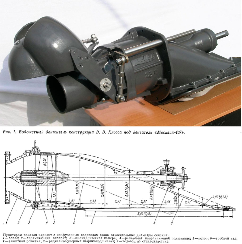
To build the motorboat (Fig. 1), I used sea sled-type contours, one of the projects of which was published in the 13th issue (Fig. 2). The hull, 4.0 m long and 1.4 m wide, is built on frames made of 10 mm plywood and a longitudinal set of pine slats. The bottom skin is made of BP-1 plywood, 3.5 mm thick, the sides - 2.5 mm thick. The body is covered on the outside with fiberglass epoxy resin. Foam blocks are glued in the bow and stern.
The planned engine from the M-62 motorcycle could not be obtained. I had to assemble it from parts of the IZH Planet engine and the MP-800 motor pump. The power of this unit was about 30 hp. pp., assembled weight 42 kg.
The propeller shaft bearing housing, the shaft itself and the bushing are remade from the corresponding parts of the tail rotor of the MI-1 helicopter, which have served their purpose. I made the propeller blades from pine and covered them with nylon on ED-5 resin. The propeller with a diameter of 1.7 m is reversible, variable pitch. The transmission to the propeller from the engine is carried out by a chain from the IZH-56 motorcycle. The engine and propeller drive are mounted on a frame made of chromosil pipes.
Since the design used ready-made parts designed for significantly higher powers, total weight The installation turned out to be quite large - about 100 kg. To simplify the fuel system, the consumable 15-liter gas tank also had to be moved to the propeller frame (Fig. 3, 4).
During the engine run-in, the propeller thrust was measured in place - when the throttle was opened 2/3, it turned out to be equal to 80 kg.
The boat was tested on Lake Kenon. At full speed, it passed through continuous thickets of reeds and grass (the speed did not drop from this), walked along the shore at a depth of 8-10 cm, without touching the bottom. The boat moved well even on a fairly high wave, it was well controlled in planing mode, the speed with one driver reached 45 km/h, with two passengers - 42 km/h.
The boat was transported to the water on a trailer behind a motorcycle. If you start the engine of a boat on a trailer, it easily pushes a motorcycle with a sidecar in front of it. So it should go just as easily on ice.
Design flaws were also revealed. The chain vibrated strongly while driving (the number of sprocket revolutions was about 5000 rpm), and the water rudder turned out to be insufficiently effective, especially at low boat speeds. Over the winter, the chain was replaced with a V-belt drive, which operates silently and can withstand high speeds. To increase traction, a profiled nozzle with a gap of 6 mm was installed around the propeller. However, it did not provide an increase in thrust; when the gap was reduced to 2 mm during transient engine conditions, the ring began to vibrate and the propeller touched it. In the future, it is planned to increase the thrust of the propeller by increasing its diameter and installing a gearbox. However, the results obtained can be considered quite good. The speed of 45 km/h with a full load of 280-300 kg and good cross-country ability completely repay the efforts spent on construction.
The main difficulty that the builder of such a motorboat may encounter is calculating the propeller. Below is a series practical recommendations on the selection of the main elements of propellers, borrowed from a number of sources (a list of them is given at the end of the article).
Screw diameter
The desire to obtain the greatest thrust and propeller efficiency forces the use of propellers large diameter or increase the speed. But both ways have their limits: an increase in diameter, as a rule, is limited by design considerations (for example, it is undesirable for the edges of the blades to protrude beyond the width of the boat), and with increasing speed, the peripheral speeds of the ends of the blades approach the speed of sound and k. The propeller pressure decreases sharply. In this case, wooden screws reach the critical rotation speed faster than metal screws (Fig. 6 and 7).An increase in diameter also worsens the stability of the motorboat, its maneuverability through reeds and reeds, reduces seaworthiness, and increases the dimensions of the installation and weight.
Typically, the diameters of propellers even with powerful engine do not exceed 2.5 m. To determine the diameter of the screw, you can use the formula:

where W k is the peripheral speed of the blade tip, m/s;
n in - number of screw revolutions per minute;
N - engine power, l. With.;
n - number of propeller revolutions per second.
It is possible to increase the thrust force without increasing the diameter, by increasing the number of blades to 3 or even 4. However, the efficiency of multi-bladed propellers is somewhat reduced due to the operation of the blades in a more disturbed flow. When calculating a multi-blade propeller, a correction factor is introduced k 2 =0,9.
To calculate the diameter of a two-bladed propeller with blades of normal width, the coefficient k 2 =1.0 (with b max =0.08÷0.09); two-blade propeller with narrow blades k 2 =1,1 (b max =0.06÷0.07); slotted two-blade propeller with very wide blades k 2 =0.14÷0.2 (everywhere b max = b max/D; b max - maximum blade width).
Shape and dimensions of the cross section of the blade
Most often, flat-convex segmental and aviation profiles are used for propellers. Main geometric characteristics profiles are the magnitude of the chord b and profile thickness WITH(Fig. 8). The relative profile thickness is the ratio c=C/b; profiles are: thick ( c=0.21÷0.15), average ( c=0.12÷0.1) and thin ( cIncreasing the width of the blade does not give any gain - due to the increase in its weight, the efficiency of the propeller decreases; this is explained by the fact that as the width increases, the thickness of the blade also increases. Characteristic cross section The propeller blade is its section at a radius equal to 0.75 R. The value of the profile chord of this section is called the average chord of the blade b 0.75. To calculate it, we can recommend the formula:

Where k- number of blades;
C y is the average lift coefficient of a given profile, determined from the graph (Fig. 9).
Having calculated the value of the average chord of the blade b 0.75, it is necessary to determine its relative width: b rel = b 0.75 / D; for wooden screws this value should be in the range from 0.08 to 0.12. Wide blades with b 0.75 >0.12 will have lower efficiency. If it turns out that the relative width of the blade does not fall within the recommended limits, it means that the propeller parameters were not chosen very well. In this case, you can change the width of the blade by changing the peripheral speed, or increase the number of propeller blades. It is better to make a propeller with the same blade width along the entire length with a rectangular wide end (Fig. 10).
The relative thicknesses of the blade profiles should be: at the hub - 0.18÷0.2, in the section at R 0.75 - 0.14÷0.13 and at the ends of the blades - 0.07÷0.1.
It is advisable to use large relative thicknesses on low-speed propellers with a blade tip peripheral speed of up to 180 m/s.
The pitch of the screw or the average installation angle of the section located at a radius of 0.75 R relative to the plane of rotation of the screw is determined by the formula:
The installation angles of the remaining sections φ n are determined by relative sizeφ taken from the graph (Fig. 11):
The propeller thrust can be determined by the formula:
where η is the propeller efficiency;
Δ - relative density air (at normal conditions numerically equal to 1);
D - screw diameter in m;
N is the power supplied to the propeller, in hp. With.
or
where K 1 for a two-blade propeller is 7.5.
In conclusion, examples of propeller calculations made for the described motorboat are given.
Calculations are given for a wooden, reversible propeller with a chain gear (screw 1) and a metal propeller (screw 2) for installation directly on the engine shaft (the angle of the blades can be adjusted when the engine is stopped).
Initial data: engine power - 30 hp. With.; crankshaft speed - 3600 rpm; gear ratio - 2.
I. Selection of screw diameter. For wooden screw 1 I chose the peripheral speed Wк=160 m/s, corresponding to the highest efficiency, then (1)

In the second case, I chose the diameter of propeller 2 for design reasons, equal to the width of the boat 1.4 m. We find the critical speed for a metal propeller with a diameter of 1.4 m from the graph in Fig. 7 n=4000 rpm, but actually 3600 rpm, therefore,
According to the graph (Fig. 6) we find the value of efficiency η = 0.6, which, of course, is less than for a wooden screw, but in this case there will be no power loss in the gearbox.
II. Determining the propeller thrust (7):
where N is taken taking into account losses in the gearbox;
This result almost coincides with dynamometer tests on mooring lines - the thrust turned out to be 80 kg.
III. Determining the width of the blade for these screws at a distance of 0.75 R (3):

In the second case, the blade turns out narrower, which is more advantageous.
IV. Determining the installation angle of the section along the blade at a distance of 0.75 R (4):

According to Fig. 11, you can determine the installation angles of the sections at any radius. If the propeller is variable pitch, then it is important to correctly only twist the blade, i.e. the angle of attack of the blade can be changed depending on the sailing conditions (I can change the pitch of a wooden propeller from -1 m to +1.5 m). If the propeller has a constant pitch, then an error in determining the pitch can lead to the fact that the engine will not pull such a propeller or will not operate at full power.
The weight of one blade of the first propeller is 2.5 kg. I cast the second screw from duralumin alloy. The weight of its blade is 3 kg.
Installing a propeller without a gearbox made it possible to reduce the weight of the propeller unit by 30 kg.
- 1. "Snowmobile". I. N. Yuvenalyev, ed. DOSAAF, 1962
- 2. Magazine “Modeler-Constructor”, No. 9, 1968, No. 11, 12 for 1970, ed. “Knowledge”, No. 11, 1967
- 3. Brochure of the “Transport” series, ed. “Knowledge”, No. 11, 1967
Airboat is great vehicle for those who often like to go fishing and hunting, because its characteristics are many times greater than the cross-country ability of any SUV. Moreover, it can be used both in summer and in winter period. True, the cost of airboats sometimes starts at 300 thousand rubles and above. But you can go the other way by making a similar product yourself.
Homemade airboats are practically not inferior in quality to their factory counterparts. Therefore, every year there are more and more of them in Russia. And today we will look at how to make an airboat with your own hands.
Engine
The motor for our homemade product can be used from the usual Soviet times. But for lovers of high speed, this will not seem enough. In this case, you should pay attention to the Japanese Honda and Yamaha engines with power from 150 to 210 horsepower. Paired with a propeller, such a motor is capable of accelerating a boat up to 50 kilometers per hour on water and up to 90 on ice. and the thermostat is taken from passenger car"Zhiguli" type. The driven and driving pulleys are made of duralumin steel.
Screws, blades and propeller
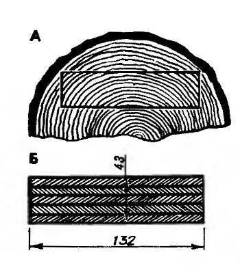
In addition to the engine, you should also take care of the airboat's propeller. We will make it from solid wooden beam. You can go the other way by gluing together several 10 mm plates. It is important that the finished element does not contain unnecessary knots and burrs. As for the plates, when fitting them, it is better to make a 1:1 drawing, which will be a kind of template, and using this data to make a boat propeller.

To make a high-quality airboat with your own hands, you should not be lazy and make everything “by eye” - each part is made according to its own template and drawing.
The propeller blades should also be free of burrs and other deformed areas. Such defects can be removed using a small hatchet. Next, the wood is processed with a plane and rasp. Transverse cuts are made on a special slipway. They are needed to install the propeller blades.
How to further make an airboat with your own hands? For the core of the slipway we need ordinary steel. The main thing is that its diameter is equal to the hole in the hub of the mentioned part. Next, the rod is placed on the center of the slipway board. Afterwards, the propeller blank is put on it and pressed against the template with several blades. This workpiece should show template marks (where the blades touch the propeller).
These places should be processed with a plane and placed back on the slipway. The blade processing process must be repeated. Next, using the upper templates, the upper part of the screw is processed. As a result, both elements must touch up to the plane of the connector. All treated areas are marked with a colored pencil or marker, after which zones are created between the control section. The correctness of the work performed is checked with a steel ruler - it is applied to the points of adjacent sections. Ideally, the gap between the ruler and the blades should be minimal.
Now the screw needs to be balanced. This is done as follows. First, a steel platen is inserted into the central hole and the propeller is mounted on the balancing rulers. If suddenly one blade turns out to be lighter than the other, it is loaded with lead (thin strips of this metal, previously poured into a mold, are glued on). The finished rod is inserted into the hole of the blade - where the lead strips were applied. It is countersunk on both sides. The propeller is covered with fiberglass on both sides, sanded, balanced and goes through a painting procedure (priming and enamel).

How to make an airboat with your own hands? Drawings and assembly of the lower body
The airboat hull consists of two parts - lower and upper. It's best to start with the first one. To do this, in accordance with the drawing, we prepare frames from 12 mm plywood sheets. The keel and stringers will be made from slats with a section of 2x2, 2x3 and 3x3 centimeters. The frames are mounted to the floor on bars and slats-braces. The slats should be adjusted to the location. They are attached to slats for the front part of the boat, undergo a preliminary procedure of steaming in boiling water, and then are tied to the frame with wire. After drying, the wood is finally fixed with glue. Next, the finished frame is leveled and filled with foam blocks. We also put the latter on epoxy resin.
If necessary, the foam is puttied with a mixture of glue and sawdust. The body itself is covered on both sides with a thin layer of fiberglass, after which it is sanded and painted. From the inside, unnecessary foam is cut off so that it stands flush with the frames. Then it is also covered with fiberglass.

Upper body
The upper part of the body is assembled slightly differently. Here we will not use plywood frames, but curved slats that will be attached to the finished lower part of the boat. Where the engine is located, the frame is fixed with gussets. The frame itself is mounted to a cross member made of steel pipe square section(4x4 centimeters) and is fixed with 2.2 cm pipes. Then everything is simple - foam is applied to the surface and covered with fiberglass. This way we will complete the procedure of forming the upper part of the hull of a homemade airboat. The doors can be made from plywood, and the windshield is best taken from a domestic car (for example, from the back door of a Moskvich).
How to make fishing crafts? Controls
A drum is installed on the steering wheel shaft, connected to a yoke on the steering wheel stock. Instead of an accelerator pedal, there will be a small lever that can be mounted in any front part of the boat's interior.

Salon
The seats for passengers and the driver are made of wood slats and plywood. The frame is filled with foam rubber and covered with leather. You can go another way - take ready-made seats from a foreign car or even a domestic car. At this stage, the question “how to make an airboat with your own hands” can be considered closed. All other little things in the cabin are arranged to your liking; the main thing here is to have imagination and enthusiasm.
So, we found out how to make an airboat with our own hands. Good luck!
Almost every fisherman dreams of having a boat, especially a boat with a motor. Some people buy a boat with a motor, while others modify their boats by installing homemade engines, since it turns out cheaper, and they can’t be installed on every boat. And yet, boat owners cope with their task. Recently, water-jet engines have begun to enjoy widespread popularity as they are more functional.
To make a water cannon, you will need any, most common type of engine. And then everything depends on the skills of the boat owner. If such an opportunity exists, then you should pay attention to such models as “SM-557-9L\\T”, “Moscow”, “Veterok”, “Strela” and others. The completed water cannon will cope with its task perfectly, regardless of which engine it is based on.

The most important advantage is the absence of rotating parts located in the water, and unprotected ones. In other words, this is the most safe type engine. In addition, the operation of the engine is difficult to disrupt by various foreign objects in the water, including aquatic plants. On a regular screw outboard motor Algae can easily get wrapped up, which cannot be said about a water cannon. In addition, moving elements are protected from various impacts, which cannot be protected from when moving along the surface of the water, especially in shallow areas.
Water cannons are considered suitable for the following typical locations:
- in the presence of shallow depths or shallow bodies of water;
- in the presence of aquatic vegetation, especially vigorous;
- on reservoirs where there are many small areas;
- on rivers characterized by the presence of rapids.
In other words, a boat with a jet engine will go where a boat with a conventional outboard motor cannot go at all, since there is a risk of damage to the motor, or rather, its propeller. The water-jet propulsion system is free of such disadvantages, since the water-jet nozzle and the intake pipe are located high in the water column. In addition, the intake pipe has a special grid, which prevents various large objects from getting inside the water cannon. Even if large algae or fragments of objects get inside the chamber, this will not affect the trouble-free operation of the motor. The grid cells are small in size, which prevents even pebbles from getting inside. The only thing that can get into the water cannon chamber is sand, which is also not able to lead to emergency conditions. Water jets have another very important factor - their blades are not subject to cavitation, which has a positive effect on their durability. Therefore, we can safely say that the water cannon has a lot of positive qualities.
Nowadays you can find some models of water cannons on sale, but they do not have good functionality. Usually, when installing them, part of the power is lost, due to which the speed of movement decreases. In addition, the maneuverability of the boat and its controllability are reduced. At the same time, the process of controlling the boat is the same as when installing a conventional outboard motor on a watercraft.

In this case, two options are available for installing the water pipeline: outside the housing or directly in the housing. Its location is the bottom of the boat. The inlet hole is located in the bow, and the structure itself is built into the hull of the boat. At the same time, you should make sure that the inlet pipe is always in the water, otherwise the water cannon may malfunction.
In fact, the design is not much different in principle from the principle of operation of an engine with a screw. There is also a screw called an impeller, which, when rotating, creates a stream of water that propels the boat.
The impeller is placed inside the water jet, the inlet and outlet holes of which are not the same. The design is equipped with a control device called reverse steering, with the help of which the water jet is directed in the desired direction, which leads to a change in the direction of movement of the boat.
The internal part of the water jet is made in a profiled version, due to which the turbulence of the water flow is reduced until it enters the impeller operating area.
The control device is capable of directing the flow of water in the desired direction. In addition, you can force the boat to sail in reverse by switching the control device to the “reverse” position. A similar function is quite useful, as it allows you to get out of difficult situations, especially if there is large quantity thickets.
As a rule, the speed of movement in reverse is much less than when moving forward, since the input and output of the device have different thickness, that is, the diameter.
How to build a jet engine for a boat yourself?
The best version of a water-jet engine is obtained by using the Veterok 12 outboard motor as a base one. This is due to the fact that this engine is provided necessary assortment spare parts. It is not difficult to purchase them at the city market or via the Internet.
After upgrading a conventional outboard motor, the total weight of the water jet will increase by only 1 kg, which is not at all significant for a boat of any type.
A working water cannon is capable of accelerating a boat with a displacement of 450 kg to 20-25 km/h, which an outboard motor of similar power is not capable of.
To upgrade a conventional outboard motor, you will need the following parts:
- Outboard motor “Veterok 12” with a special flange.
- Gearbox.
- Reamers of the water collector.
- Welding machine.
- Hub.
- Special glue (waterproof).
- Fittings.
- Engine diagram (drawing).

Preparatory work should be carried out responsibly and carefully, otherwise you can easily damage the motor. You should not resort to using unreliable materials other than those that meet all requirements.

The design of the water collector provides a recess, which provides the boat with the necessary maneuverability and maneuverability, and also reduces hydrodynamic resistance. This is achieved due to the fact that the upper leading edge is 35 mm below the bottom level.
To assemble the motor yourself, you need to have a regular gearbox, which is fixed to the engine using a special flange. After this, you need to take a metal blank on which to draw a development of the shell, water collector and six blades.
To make workpieces of the required shape, a file and bending rollers are used. Despite this, they can also be made manually, using a mandrel. After this they begin welding work for welding longitudinal and transverse seams of the drainage system and the water jet chamber, having different shapes.
The design of the water jet includes a hub located on the boss of the product.
Water cannon in assembled form reaches a mass of 20 kg. At the same time, a drawing of such a water cannon is extremely rare. But this does not mean that such a design cannot be made yourself. If you go to the Internet, you can find any drawing here by selecting suitable option from a huge variety. The main thing is that a boat with a jet engine has much better performance characteristics.

Assembly homemade motor PVC for a boat is no more difficult than for other types of boats, but on the contrary, it is somewhat simpler. This is due to the fact that any outboard motors, with a capacity of 15 to 20 horses. In addition, purchasing such outboard motors is not problematic, and their reliability is quite high. You should pay attention to the wide range of similar products, which allows you to choose the appropriate option.
At the same time, attention should be paid to models with the lowest weight, which is especially important. In this regard, preference should be given to imported models, although similar outboard motors are also produced domestic manufacturer. At the same time, it’s no secret that domestic models are not as reliable as foreign ones. In addition, they are characterized by quieter and more economical operation.
To build a jet engine for a PVC boat, you should purchase the following components:
- Outboard boat motor.
- Special gearbox.
- Special flange.
- Hub.
- Welding machine.
- Development of the water collector.
- Engine drawing.
- Fittings.
- Waterproof glue.
The technology of converting a conventional outboard motor into jet engine the same as when making a water cannon for a regular boat.
Preparatory procedures
This is a very important stage in creating a water cannon for a PVC boat, since right actions its operational capabilities will depend. At the same time, it is necessary to take into account such a moment as the presence special tool, as well as the availability of materials that meet the stated technical characteristics.
As a rule, such work is not considered particularly difficult and almost any boat owner can handle it if they wish.

As a rule, the inlet part of the pipe should be 1.5 times larger in diameter than the conduit itself. When crossing very shallow areas, 0.1-0.15 meters deep, rare tremors are possible, which indicates an insufficient amount of water entering the water cannon. It is at this moment that it can clog. This is due to the fact that in particularly small areas the pipe can capture silt or sand, along with the presence of other objects. To prevent this from happening, it is necessary to provide an input filter.
In order for the structure to work properly, it is advisable to manufacture it according to the drawings. Finding them will not be difficult, especially if you have the Internet. Although options with unfinished drawings are possible. That is, there are possible drawings according to which the water cannons were not manufactured and their performance was not tested. Such work requires special tools and special skills in working with materials and tools.
The water jet for a PVC boat operates in a normal transition mode, capable of bringing the boat to planing at a speed of 13-17 km/h. The efficiency factor (COP) of such structures is no less than 50%, which is quite acceptable and something that the classic type of outboard motor cannot boast of.
The operation of a water jet is based on the following principle: water is pumped into the working chamber through a water collector due to the operation of blades located on the impeller (impeller). As a result of such work, excessive pressure is formed in the chamber. After which, water under pressure is released from the working chamber, which ensures the movement of the boat. In this case, the principle of jet propulsion used in turbojet engines is used. This occurs due to the difference in the diameters of the inlet and outlet openings, as well as the presence of a turbine: in our case, it is an impeller. The impeller rotates due to a cardan drive coming from the boat engine.
The design feature is that PVC boat can be operated at any depth, including the smallest, which is unacceptable with a conventional outboard motor.
In this case, it is very important to match the motor power directly to the dimensions of the boat and its weight. This means you need to know specifications watercraft. There may be cases when it will not be possible to install this type of engine due to technical condition boats. At the same time, do not forget that being on the water with faulty elements is very dangerous.
Conclusion
If you carefully delve into the topic, then making a water jet for a boat with your own hands is not a problem, which is what many owners of watercraft do. Experience shows that if all necessary details and tools, it is possible to assemble a working water jet engine in 2-3 hours.
Naturally, many are engaged in manufacturing not because of a good life, since they constantly have to save on something. To buy a ready-made jet engine and install it on your boat, you will have to pay a large amount money. But this is not a fact that it will work efficiently and reliably, especially if it is a model from a domestic manufacturer.
The use of a water jet allows you to save money and gasoline, since it is more efficient than a conventional boat motor. Besides, water jet propulsion safer in any case, both for those around you and for those who exploit it.