MINISTRY OF EDUCATION AND SCIENCE OF THE RUSSIAN FEDERATION
NOVGOROD STATE UNIVERSITY NAMED AFTER YAROSLAV THE WISE
Kuznetsov N.P.
STUDYING THE DESIGN, OPERATION AND DETERMINATION OF THE LOADING CAPACITY OF WORM REDUCERS
Guidelines for laboratory work
VELIKIY NOVGOROD
Published by decision of RIS NovSU |
REVIEWER Candidate of Technical Sciences, Associate Professor E. I. Nikitin
Kuznetsov N.P.
K93 Study of the design, operation and determination of the load capacity of worm gearboxes: Method. decree. for laboratory work on EBM and OK /Auth. – comp. Kuznetsov N.P.; NovSU named after. Yaroslav the Wise. - Veliky Novgorod, 2012. – 23 p.
The device has been reviewed design features, geometric parameters, assessment of the load-bearing capacity of a single-speed worm gearbox for general purpose.
Guidelines are intended for students of specialties 151001.65 “Mechanical Engineering Technology”, 190601.65 “Automobiles and Automotive Industry”, 110301.65 “Mechanization Agriculture", 150201.65 "Machinery and technology of metal forming", 50502.65 "Technology and entrepreneurship" of all forms of education and students in the areas 151900.62 "Design and technological support of machine-building production", 190600.62 "Operation of transport and technological machines and complexes", 110800.62 "Agroengineering", 140100.62 “Thermal power engineering and heating engineering”, 540500.62 “Technological education”.
UDC 621.81 BBK 34.445.1
© Novgorodsky State University, 2012
© N.P. Kuznetsov, 2012
1. Purpose of the work
– Get acquainted with the design of the worm gear single-stage gearbox and the purpose of its parts;
– determine the geometric parameters of the worm gear by measuring and calculating them;
– evaluate the load capacity of the gearbox;
– evaluate the efficiency of a worm gearbox.
Laboratory work is completed within 2 hours. Extracurricular preparation for work includes familiarization with methodological instructions and studying the relevant sections of the machine parts course using lecture notes and specified literature.
2. Description of the worm gear design
A worm gearbox is a mechanism designed to reduce angular velocity and increase torque. It consists of one or more worm gears mounted in a closed housing. In the range of gear ratios u = 8 – 80, single-stage gearboxes are mainly used.
Worm gear refers to gear-screw gears and consists of worm 1 (Fig. 1), i.e. a short screw with a trapezoidal or similar thread, and a worm wheel 2 with arc-shaped oblique teeth covering part of the worm. It is used to transmit rotational motion between shafts with intersecting axes from the high-speed input shaft of the worm to the low-speed output shaft of the worm wheel.
The main kinematic parameter worm gear is re-
date relation u 12: | ||||||||
where ω 1 , ω 2 – angular velocities; | n 1 ,n 2 – rotation speeds corresponding |
|||||||
worm and wheel; z 2 – number of worm wheel teeth, z 1 – number of worm starts (number of worm screw threads).
IN mechanical engineering uses gearboxes with different arrangements of worms: with the bottom (at a peripheral speed of the worm up to 4–5 m/s - Fig. 2.a;
With top - fig. 2.b; with lateral - Fig. 2.c and vertical Fig. 2.d.
IN Depending on the shape of the outer surface of the worm, gears can be cylindrical (Fig. 1,a), globoid (Fig. 1.b). Each of them has its own cutting technology. Globoid transmission is characterized by increased efficiency and higher load-bearing capacity due to an increase in the length of the contact line, but at the same time it is more difficult to manufacture, assemble and is more
sensitivity to axial displacement of the worm caused by bearing wear.
Fig.2. Options for the relative position of the worm and wheel in a worm gearbox
According to the shape of the lateral surface of the transmission coil, there are three types: with Archimedean (ZA), convolute (ZN) and involute (ZI) worms. The choice of worm profile is determined by technological considerations. In mechanical engineering, Archimedean worms are most widely used. Their manufacture does not require special machines, but grinding the coils is difficult, because I require

there are grinding wheels shaped profile. Archimedean worms are used when the hardness of the material is HB ≤ 350.
Involute and convolute worms are used for high hardness of working surfaces (at least 45HRC), because grinding them after heat treatment is not associated with technical difficulties.
The direction of the worm turns can be right or left. Mostly right-handed worms are used.
The main geometric parameters of the worm gear - engagement module m, number of worm engagements z 1 and wheel teeth z 2, worm diameter coefficient q, nominal value of the gear ratio u nom and center distance a W are regulated by GOST 2144.
In worm gears, the module m=p/π (here p is the axial pitch of the worm). For a worm this module is axial, for a wheel it is end module. Along with the worm screw pitch for multi-start worms, the screw stroke is considered equal to the axial movement of the helix profile point per revolution: p h =p· z 1. Pitch diameter wormd 1 =q·m. The worm diameter coefficient q shows how many modules make up the pitch diameter of the worm.
The main dimensions of the worm wheel include: pitch diameter d 2 = m· z 2, vertex diameter d a2 = m · (z 2 +2), largest outer diameter of the wheel rim (workpiece diameter) d aM2, nominal wrap angle 2δ. (Fig.3)
Fig.3. The main dimensions of the worm and the rim of the worm wheel
When the transmission operates, the turns of the worm slide between the teeth of the wheel. In addition, the worm gear is dominated by a zone unfavorable for hydrodynamic

namical lubrication (sliding occurs along contact lines, which makes it difficult to form an oil wedge in the kinematic pair). As a result, large friction forces arise in the engagement, to reduce which the contacting surfaces of the transmission links are made of antifriction materials that reduce abrasive wear and friction losses. Bad conditions lubricants lead to the danger of jamming (molecular mechanical wear), which depends on the speed of sliding of the worm turns on the wheel teeth. The higher this speed, the greater the danger of jamming and the greater must be the difference in hardness of the materials from which the worm and wheel are made. In most cases, worms are made integral with a shaft made of steels 45 and 40X with surface hardening to HRC 45...55.
Gear rims 1 of the worm wheel (Fig. 4) are made separately from the cast iron or steel center - hub 2. The choice of the grade of rim material depends on the sliding speed and duration of operation. At Vs = 6...25m/s and long work tin bronzes of the BrOF10-1 and Br.ONF10-1-1 grades are used, with Vs = 2...6 m/s aluminum-iron bronzes Br.AZh9-4 are used, with Vs< 2 м/с червячные колеса изготовляются целыми из серых чугунов марок СЧ 15-32, СЧ 18-36 и др.
Fig.4. Methods for connecting a ring gear to a wheel hub Three types of worm gear designs are used in mechanical engineering
wheels: banded (Fig. 4, a), bolted (Fig. 4, b) and bimetallic (Fig. 4 c). The latter design is the most rational, and it is used in mass-produced gearboxes.
The design of worm gearboxes with lower and upper worm locations is shown in Fig. 5 and 6. The gearbox housing with a lower worm position is made in the form of a split box to facilitate assembly.
It consists of a lower part 1, which is called the body, and an upper part 2 - the cover. The body and cover are connected with screws 3. The relative positions of the cover and body are fixed with conical pins 4 in Fig. 5.
Housing 1 of the gearbox shown in Fig. 6, made in one piece. The holes in the housing allow the free installation of shaft 2 with mounted parts (worm wheel 3, bushings, bearings 4). In the upper part of the housing there is a hatch through which oil is poured and the condition of the gear teeth and turns of the worm 5 is monitored. The hatch is closed with a lid 6, which has an vent 7, designed to equalize the pressure inside the housing and outside, otherwise the heated air would be squeezed out together during operation of the gearbox with oil due to excess pressure through the seals, and oil smudges would form on the body. The shafts 2 and 5 of the gearbox are supported by rolling bearings 4 and 8 (conical roller angular contact), holding the rotating parts in the desired position. proper operation mutual position.
When working in a worm gear, a force arises that can be represented by three mutually perpendicular components: circumferential F t , radial F r and axial F a forces (Fig. 7). Moreover, the circumferential force on the worm is equal to the axial force on the worm wheelF t1 = F a2. The radial forces on the worm and wheel are equal to F r1 = F r2. The circumferential force on the wheel is equal to the axial force on the wormF t2 = F a1. All these forces are transmitted to the housing and cover through rolling bearings.
Worms with a small distance between the supports in thermally unstressed gears can be installed on angular contact bearings one at a time in the support (installation by surprise), as shown in Fig. 5 and 6. If the worm has long distance between supports (usually with center distances A Fig.7. Forces acting in the worm gear
No. 3 Worm gearbox.doc
Laboratory work 3DISASSEMBLY AND ASSEMBLY OF A WORM REDUCER
Goal of the work: practical study of the designs of worm gearboxes, determination of worm gear parameters, measurement of overall and connecting dimensions of gearboxes, familiarization with adjusting clearances in bearings and adjusting worm gearing.
1. Purpose of the gearbox
Worm gearboxes serve to reduce the rotation speed of the output shaft and correspondingly increase the torque on it. They are used to transmit rotational motion between shafts whose axes cross at an angle of 90 0 . Most important characteristics gearbox are the torque on the low-speed shaft, the efficiency, and the rotational speed of the high-speed shaft.
The main advantages of worm gears:
Possibility of implementing large gear ratios in one stage
(for power transmissions from 8 to 80, for kinematic ones up to 1000), smooth and silent operation, the possibility of self-braking.
The main disadvantage of the worm gear is its relatively low efficiency. Associated disadvantages include significant heat generation in the area of engagement of the worm with the worm wheel, a tendency to jam in the engagement, the need for use for rims worm wheels expensive antifriction materials, increased wear. These disadvantages limit the use of worm gearboxes in terms of power (usually up to 80 kW and less often up to 300 kW)
Worm gearboxes are most widely used in hoisting and transport machines, in machine tool gearboxes, and in steering mechanisms. Vehicle, i.e. in periodic mechanisms at relatively low speeds.
^
2. Design of worm gearboxes
The most widely used are single-stage worm gearboxes. Based on the relative location of the worm and the worm wheel, three main schemes of worm gearboxes are distinguished: with a lower (Fig. 1.a), upper (Fig. 1.b) and lateral (Fig. 1.c, d) worm location.
Rice. 1. Schemes of worm gearboxes
Gearboxes for general machine-building applications with an axle distance from 40 to 500 mm are usually made of two types: with a worm under the wheel - RChP and above the wheel - RChN.
TO 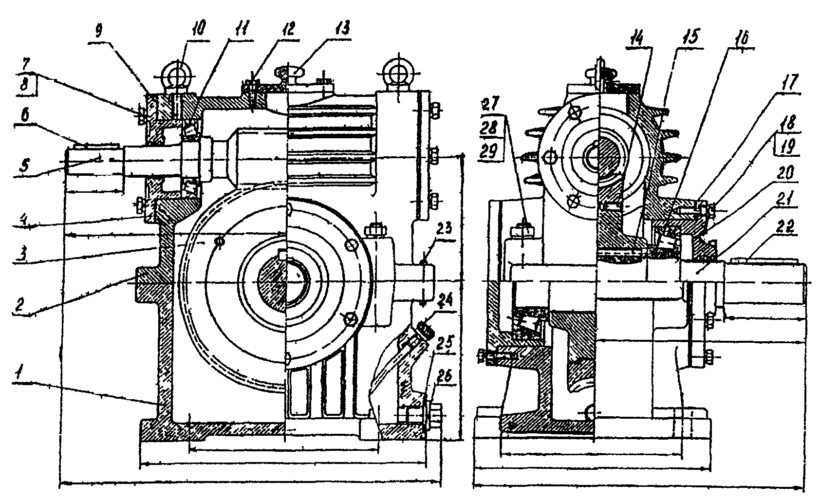
housings for relatively small worm gearboxes with center distances up to 100 mm. They are most often made without a connector (type RFU40....RFU100). Gearboxes with center distance 125mm. and more usually have housings with a connector along the axis of the worm wheel (Fig. 2).
Rice. 2. Worm gear with top position worm
Main details in Fig. 2: 1 -frame; 2-body cover; 3-worm wheel; 4.20 - through bearing caps; 5 - worm; 11.16 - bearings; 13 - inspection hatch cover; 21 - low-speed shaft; 23 - pin; 24 - oil indicator screw; 26 - drain plug; 9.17 - set of gaskets.
In worm gearboxes, rolling bearings are usually used for shaft support. In gearboxes with center distance up to 160mm. worms are usually installed in angular contact bearings, one in each support (installation “by surprise” - see Fig. 2). With center distances greater than 200mm. In one of the worm supports, two angular contact bearings are installed, which absorb axial load in both directions, and in the other support there is a floating radial bearing. To support the wheel shaft, they usually use one angular contact bearing on each side, which is installed “by surprise”. The inner rings of the bearings are placed on the shafts with interference to prevent rotation of the ring on the shaft journal, and the outer rings are placed in the gearbox housing according to a transitional fit or with a minimum gap to perform axial adjustment of the bearings and adjust the engagement along the contact patch.
The main way to lubricate a worm gear is to dip the worm or wheel into an oil bath in the gearbox housing. The oil bath must have sufficient capacity to prevent rapid aging of the oil and the movement of wear products and deposits into the gearing and shaft support. With a lower worm position, the oil level is usually set based on the condition of complete immersion of the worm turns. The oil level for the upper position of the worm is determined based on the condition of complete immersion of the worm wheel tooth.
In high-speed, high-power worm gearboxes, circulation lubricant is used. Oil level indicators are used to control the oil level. To fill the oil and check the contact patch, use the inspection hatch (Fig. 2.) or the top cover of the gearbox. A plug is installed in the lower part of the gearbox housing to drain the oil. Through the vent on the inspection hatch cover in gearboxes of the RChN or RChP type, the air pressure inside the gearbox housing is equalized with respect to the outside. In RFC type gearboxes, a hole is provided in the oil level dipstick for this purpose.
To eliminate oil leaks and dust and dirt getting inside the gearbox, seals are installed in the through covers of the gearbox supports. The most commonly used seals are lip type seals.
Material of main gearbox parts
The cover and housing of the gearboxes are usually made of gray cast iron or AL-3 aluminum alloy.
The worm is made from structural steel grades (steel 45, steel 40, steel 20, steel 20Х) for lightly loaded gearboxes and from alloy steel grades (steel 40ХН, steel 34ХН1М, steel 38ХГН, steel 5ХНВ...) for heavily loaded gearboxes. Worms are usually subjected to a general heat treatment of 260-290 HB or a general heat treatment of 230-260 HB and surface hardening of the teeth of 42-48 HRC. Last option is more preferable, but after surface hardening, grinding on special machines is necessary. Worms made of low-carbon steel grades (20, 20Х, 20ХГ) are subjected to carburization followed by surface hardening.
In order to reduce the coefficient of friction and prevent gear jamming, worm wheels are made, as a rule, from bronze BrAZh9-4L, BrOF10-1, etc. Less commonly, they are made from cast iron, antifriction aluminum alloys and plastics. In the manufacture of wheels with a diameter of more than 150-200mm. In order to save money, only the ring gear is made of bronze, and the wheel disc is made of cast iron or carbon steel. There are many ways to connect a crown to a disk, but the most common are pouring the crown directly onto a pre-grooved wheel disk or placing the crown on the disk with tension and installing threaded gougons along the surface of the joint.
^
3. Determination of the main parameters of the worm gearbox
The main parameters of the worm gearbox are: gear ratio - u; center distance - a w; number of worm turns - z 1 ; engagement module- m.
The number of turns of the worm (the number of starts) can be determined by looking at the worm from the end: how many threads of thread start from the end of the screw, the number of turns the worm has.
The gear ratio is determined by the relation u= z 2 / z 1 , Where z 2 - number of teeth of the worm wheel.
Engagement module (axial )  ,
Where P- axial step of the worm.
,
Where P- axial step of the worm.
Worm helix angle  , Where:
d a 1 = (d 1 2 m) - outer diameter of the worm, d 1 - pitch diameter of the worm.
Center distance  , Where d 2
- pitch diameter of the wheel.
, Where d 2
- pitch diameter of the wheel.
d 2 = mz 2 ; z 2 - number of teeth of the worm wheel.
Worm gear efficiency  Where
Where  - reduced friction angle in engagement.
Efficiency increases with increasing number of worm turns z 1
and with a decrease in the friction coefficient f(or friction angle).  .
.
Approximate value of the friction coefficient f can be taken for a ground steel worm and provided that the worm pair works with immersion in an oil bath:
Tin bronze wheel crown f = 0.03 - 0.05.
Wheel crown made of bronze type BrAZh-9-4L f = 0.05 - 0.07.
With more accurate calculations it is recommended to accept the values  And
And  depending on the sliding speed in the mesh, from the expression
  , Where:
  - angular velocity worm (rad/s).
d 1
- pitch diameter of the worm in mm.
Equipment and accessories
:
Worm gearbox, wrenches, metal ruler 0...500 mm, caliper 0...250mm, protractor, black paint, brush, solvent.
^
4. Work order
Measure the distance between the worm axis and the worm wheel axis (see Fig. 2).
Disassemble the gearbox: unscrew the bolts of the end covers, unscrew the fasteners of the cover and housing, remove the gearbox cover and end covers, remove the worm and worm wheel along with the bearings.
Familiarize yourself with the design and purpose of parts.
Produce necessary measurements details (Fig. 3.).
Draw a kinematic diagram of the gearbox.
Draw a freehand sketch of the general view of the gearbox (Fig. 2).
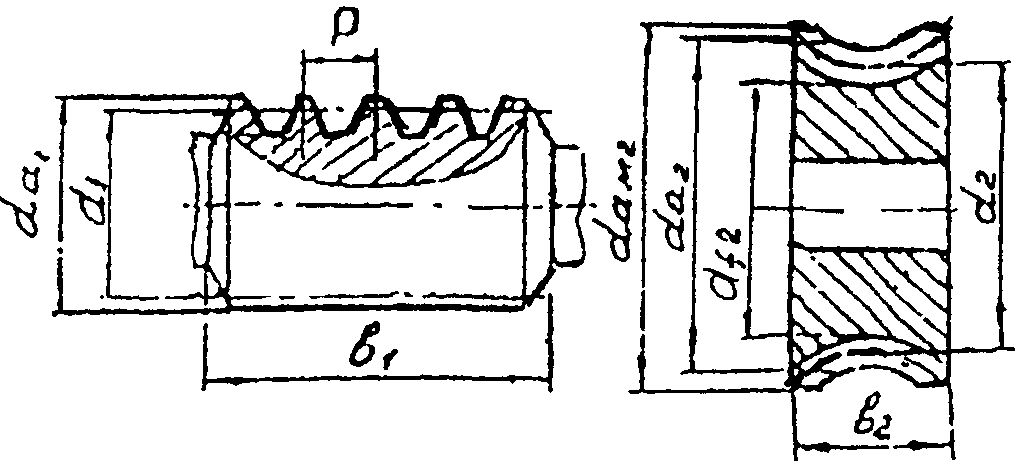
Fig.3. Main dimensions of worm and worm wheel
Checking for correct engagement
For proper engagement of the worm pair, it is necessary that the middle plane of the worm wheel passes through the center of the worm. This condition can be checked by the contact patch (Fig. 4).

Rice. 4. Spot position
Contact
If it is symmetrical relative to the main plane (Fig. 4b.), then the engagement is correct. If it is shifted to the right (Fig. 4.a), or to the left (Fig. 4.c), then it is necessary to opposite side Remove one gasket from under the cover and place it on the other side. In this case, the wheel with the shaft and bearings will move to the left or to the right. When choosing the thickness of the spacers, you should install the wheel symmetrically relative to the worm.
Checking the contact patch is done using paint, which is applied in a thin layer to the surface of the worm turns. After assembling the gearbox, the worm turns. The contact patch is controlled by the imprint on the working surface of the wheel teeth. After checking the correct engagement, it is necessary to remove traces of paint from the worm and from the worm wheel.
The gearbox is assembled in reverse order disassembly process. Special attention Care should be taken to adjust the angular contact bearings. The amount of axial clearance for angular contact bearings with an internal diameter of 30...50mm. is 0.05...0.12mm. The gap size is adjusted using spacers.
^
5. Contents of the report
The report is executed on standard sheets paper size 210 by 290 mm. On title page number and name are indicated laboratory work, name of the department, group number and surname of the performer, date.
The report should include:
kinematic diagram and sketch of the general view of the gearbox with overall and connecting dimensions,
table for determining the main parameters of the gearbox,
gearbox characteristics,
specification of the main gearbox parts,
description of the design of the gearbox, the method of checking the contact patch in the mesh and adjusting the bearing supports.
Kinematic diagram of the gearbox (see Fig. 1).
Sketch of the general view of the gearbox with overall and connecting dimensions (see Fig. 2).
Table of measured gearbox parameters
| Parameter name | Designation | Units |
| Center distance | a w | mm |
| Number of worm turns | z 1 | |
| Axial step of the worm | P | mm |
| Number of wheel teeth | z 2 | |
| Outside diameter worm | d a1 | mm |
| Worm wheel outer diameter | d aM2 | mm |
| Worm wheel width | b 2 | mm |
Table of calculated parameters
| Parameter name | Calculation formula | Unit change | Result |
| Gear ratio | u = z 2 /z 1 | ||
| Axial engagement module | m = P/  | mm | |
| Worm pitch diameter | d 1 =d a1 - 2m | mm | |
| Helix angle of the worm |  | hail | |
| Worm diameter coefficient | g = d 1 /m | ||
| Worm wheel pitch diameter | d 2 = m z 2 | mm | |
| Worm pair efficiency | | ||
Specification of main gearbox parts.
| Item no. | the name of detail | Quantity | Material | Note |
| 1 | Gear housing | 1 | Sch15-32 | |
| 2 | Gearbox cover | 1 | Sch15- 32 | |
| 3 | Worm wheel crown | 1 | Br. AZh9 - 4L |
and so on (main details).
Description of the gearbox, gear adjustment and bearing adjustment.
Control questions
Purpose and areas of application of worm gearboxes.
Advantages and disadvantages of worm gears in comparison with gears.
What is the number of turns (entries) of the worm?
What is the engagement module and how to measure it on a worm?
What is the total height of the tooth in modules?
Friction in worm gears and ways to combat it.
Worm and worm wheel materials.
Design of worm gearboxes.
Adjusting the worm gear according to the contact patch.
Adjusting clearances in bearings of worm gearboxes.
Ways to increase heat transfer during gearbox operation.
The most widely used are single-stage worm gearboxes. Based on the relative position of the worm and the worm wheel, three main designs of worm gearboxes are distinguished: with a lower (Fig. 1.a), upper (Fig. 1.b) and lateral (Fig. 1.c, d) worm location.
Rice. 1. Schemes of worm gearboxes
Gearboxes for general machine-building applications with an axle distance from 40 to 500 mm are usually made of two types: with a worm under the wheel - RChP and above the wheel - RChN.

Housings of relatively small worm gearboxes with center distances up to 100mm. They are most often made without a connector (type RFU40....RFU100). Gearboxes with center distance 125mm. and more usually have housings with a connector along the axis of the worm wheel (Fig. 2).
Rice. 2. Worm gearbox with top-mounted worm
Main details in Fig. 2: 1 -frame; 2-body cover; 3-worm wheel; 4.20 - through bearing caps; 5 - worm; 11.16 - bearings; 13 - inspection hatch cover; 21 - low-speed shaft; 23 - pin; 24 - oil indicator screw; 26 - drain plug; 9.17 - set of gaskets.
In worm gearboxes, rolling bearings are usually used for shaft support. In gearboxes with center distance up to 160mm. worms are usually installed in angular contact bearings, one in each support (installation “by surprise” - see Fig. 2). With center distances greater than 200mm. In one of the worm supports, two angular contact bearings are installed, which absorb axial load in both directions, and in the other support there is a floating radial bearing. To support the wheel shaft, they usually use one angular contact bearing on each side, which is installed “by surprise”. The inner rings of the bearings are placed on the shafts with interference to prevent rotation of the ring on the shaft journal, and the outer rings are placed in the gearbox housing according to a transitional fit or with a minimum gap to perform axial adjustment of the bearings and adjust the engagement along the contact patch.
The main way to lubricate a worm gear is to dip the worm or wheel into an oil bath in the gearbox housing. The oil bath must have sufficient capacity to prevent rapid aging of the oil and the movement of wear products and deposits into the gearing and shaft support. With a lower worm position, the oil level is usually set based on the condition of complete immersion of the worm turns. The oil level for the upper position of the worm is determined based on the condition of complete immersion of the worm wheel tooth.
In high-speed, high-power worm gearboxes, circulation lubricant is used. Oil level indicators are used to control the oil level. To fill the oil and check the contact patch, use the inspection hatch (Fig. 2.) or the top cover of the gearbox. A plug is installed in the lower part of the gearbox housing to drain the oil. Through the vent on the inspection hatch cover in gearboxes of the RChN or RChP type, the air pressure inside the gearbox housing is equalized with respect to the outside. In RFC type gearboxes, a hole is provided in the oil level dipstick for this purpose.
To eliminate oil leaks and dust and dirt getting inside the gearbox, seals are installed in the through covers of the gearbox supports. The most commonly used seals are lip type seals.
Material of main gearbox parts
The cover and housing of the gearboxes are usually made of gray cast iron or AL-3 aluminum alloy.
The worm is made from structural steel grades (steel 45, steel 40, steel 20, steel 20Х) for lightly loaded gearboxes and from alloy steel grades (steel 40ХН, steel 34ХН1М, steel 38ХГН, steel 5ХНВ...) for heavily loaded gearboxes. Worms are usually subjected to a general heat treatment of 260-290 HB or a general heat treatment of 230-260 HB and surface hardening of the teeth of 42-48 HRC. The latter option is more preferable, but after surface hardening, grinding on special machines is necessary. Worms made of low-carbon steel grades (20, 20Х, 20ХГ) are subjected to carburization followed by surface hardening.
In order to reduce the coefficient of friction and prevent gear jamming, worm wheels are made, as a rule, from bronze BrAZh9-4L, BrOF10-1, etc. Less commonly, they are made from cast iron, antifriction aluminum alloys and plastics. In the manufacture of wheels with a diameter of more than 150-200mm. In order to save money, only the ring gear is made of bronze, and the wheel disk is made of cast iron or carbon steel. There are many ways to connect a crown to a disk, but the most common are pouring the crown directly onto a pre-grooved wheel disk or placing the crown on the disk with tension and installing threaded gougons along the surface of the joint.
n1.doc
Worm gearboxes
Worm gearboxes are used to transmit motion between shafts whose axes intersect.
Based on the relative position of the worm and the worm wheel, three main designs of worm gearboxes are distinguished: with a lower, upper and lateral worm position (Fig. 2.14 - 2.16).
Artificial airflow of the ribbed housings provides a more favorable thermal operating conditions for the gearbox (Fig. 2.14, V And G).
The output of the gear wheel shaft with a side-mounted worm, depending on the purpose and layout of the drive, can be made upward (Fig. 2.16, A) or down (Fig. 2.16, b And V).
With the lower position of the worm, the conditions for lubrication of the gearing are better, with the upper position it is worse, but there is less chance of metal particles - wear products - getting into the engagement.
The choice of gearbox design is usually determined by the convenience of the drive layout as a whole: at peripheral speeds of the worm up to 4-6 m/s, the lower location of the worm is preferable; At high speeds, oil mixing losses increase, and in this case the worm should be positioned above the wheel. In gearboxes with an overhead worm, when turned on, the movement
Rice. 2.14. Worm gear with bottom worm:
A - kinematic diagram; 6 - general view of the gearbox with a split housing; V - general form gearbox with a ribbed split housing and artificial airflow; G - the same, with the cover removed; d - general view of a gearbox with a one-piece housing


Rice. 2.15. Worm gear with top worm:
A– kinematic diagram: b - general view of the gearbox with a split housing;
V- general view of the gearbox with a one-piece housing
It usually starts when there is insufficient lubrication (during stopping with rare starts, the oil has time to drain from the wheel teeth).
The gear ratios of worm gearboxes usually range within and = 8 80 (see GOST 2144-76).
Since the efficiency of worm gearboxes is low, to transmit large
Capacities and in installations operating continuously, it is impractical to design them. In practice, worm gearboxes are used to transmit power, as a rule, up to 45 kW and, as an exception, up to 150 kW. 
Rice. 2.16. Worm gear with vertical shaft worm wheel:
A - kinematic diagram; b- general view of the gearbox with a split housing;
V-general view of the gearbox with a one-piece housing
Tooth-worm, worm-tooth
and two-stage worm gearboxesDiagrams and general view of gear-worm and two-stage worm gearboxes are shown in Fig. 2.17 and 2.18. Gear ratios gear-worm-
Rice. 2.17. Two-stage worm gear reducer:
A - kinematic diagram; b- general form 
Rice. 2.18. Two-stage worm gear:
A - kinematic diagram; b And V– general options
New gearboxes u 150, and in some cases even higher (for educational design it is recommended to limit And= 35 80).
Two-stage worm gearboxes are manufactured with gear ratios And= 120 2500 (for educational design it is recommended to limit And= 120 400).
Planetary and wave gearboxes
In Fig. 2.19, and shows a simple - with one degree of freedom - planetary gear consisting of a sun wheel 1,
satellites 2
and crown wheel 3,
fixedly fixed in the body. Satellites do difficult things 
Rice. 2.19. Single stage planetary gearbox:
A- kinematic diagram;
b- general form
d  motion: they roll around the sun wheel and rotate inside a stationary crown wheel (some analogy with the movement of the planets gives the name to these gears). The satellite axles are installed in the carrier 4,
the geometric axis of which coincides with the geometric axes of the central wheels - solar and crown. More often than others there are transmissions with the number of satellites n c = 3.
motion: they roll around the sun wheel and rotate inside a stationary crown wheel (some analogy with the movement of the planets gives the name to these gears). The satellite axles are installed in the carrier 4,
the geometric axis of which coincides with the geometric axes of the central wheels - solar and crown. More often than others there are transmissions with the number of satellites n c = 3.
P
Rice. 2.20.Kinematic diagram of a two-stage planetary gearbox
Planetary gears are more compact than conventional gears, since when P With
in satellites, torque is transmitted not by one, but by several streams;
In strength calculations, the following are usually taken:
New number of satellites n c = n s - 0.7.
To equalize the load across the flows with several satellites, one of the central wheels is installed without supports, i.e., floating in the radial direction. In Fig. 2.19, b a gearbox with a floating (self-aligning) sun wheel is shown. To connect the floating sun wheel to the shaft, a gear coupling with two toothed joints is used.
By connecting several simple planetary gears in series, you can obtain a gearbox with a large gear ratio (Fig. 2.20).
Wave gears can be considered as a type of planetary gears that have a flexible intermediate wheel that is deformed when transmitting torque.
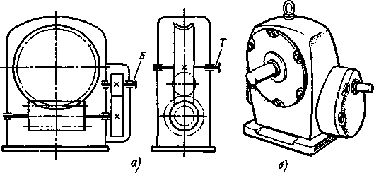
In Fig. 2.21, A shows the kinematic diagram of the wave transmission: input shaft 1 rotates the wave generator 2 , which is a carrier with two rollers; flexible wheel 3 made in the form of a thin-walled glass, on the thickened part of which there are cut teeth that engage with the internal teeth of a fixed rigid wheel 4; output shaft 5 connected to the base of a thin-walled glass.
The generator deforms flexible gear in the radial direction, giving it the shape of an ellipse, and engages the teeth of the parts 3 And 4 to full working height.
When the generator rotates, the gearing of the teeth moves like a traveling wave, which gives these gears their name.
Cam wave generators are widely used (Fig. 2.21, b). On a profiled cam A planted inner ring flexible bearing B. The outer ring of the flexible bearing is mated to the inner surface of the flexible wheel IN, providing it with a given form of deformation. The rings of a flexible bearing are thin and therefore relatively easily deformed. Below are the dimensions of two bearings with the same inner diameter for comparison: flexible and conventional radial ball bearings of the light series: 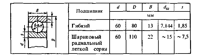
Modules gear wheels 3 and 4(see Fig. 2.21, A) are the same, but the number of teeth
z 3
u = ____________ .
z 4 – z 3
Various: z 3 
Rice. 2.21. Wave gear single-stage reducer:
A - kinematic diagram; b - wave generator: V - lengthwise cut
At optimal values(z 4 - z 3) = 2 or 1 range gear ratios in single-stage wave gearboxes ranges from 80 to 300 (or more). Wave gears have a high load capacity due to the multiple pairs of gearing: up to 25-30% of pairs of teeth can be engaged simultaneously.
In Fig. 2.21, V shown wave reducer with cam wave generator 2 and a flexible thin-walled wheel 3 welded structure. On the drive shaft 1 there is a cam on which a flexible bearing is mounted, mated to a flexible wheel, the teeth of which in two zones mesh with the teeth of the rigid wheel 4. The wave generator cam is located on the shaft with radial clearance; The transmission of motion is carried out by a gear coupling, which ensures self-alignment of the generator during operation of the gearbox. From the flexible wheel, torque is transmitted by splines to the driven shaft 5.
Gearboxes and geared motors are used to reduce the speed of the output shaft. The gearmotors are equipped with various ways fastening the flange motor to the gearbox housing.
Gearbox with bottom worm arrangement
For assembly of the gearbox, holes are provided in its solid body. The worm is threaded onto the input shaft, onto which the bearings are mounted with an interference fit. One shaft support is fixed against axial displacement and is a combination of two roller angular contact tapered bearings, the second support is floating in the axial direction. The supports along with the glass are inserted into the body from left to right. Under the lid of the cup there is a set of metal spacers to adjust the axial play of such bearings. The nut at the end of the worm shaft serves to secure such bearings and transmit the axial force arising in the worm gear. On the output shaft, a worm wheel and roller angular contact tapered bearings are installed with interference according to the thrust pattern. The shaft assembly with the worm wheel and bearings is inserted into the housing. The bearings and worm gear are adjusted using a set of metal shims located under the worm wheel shaft support caps.
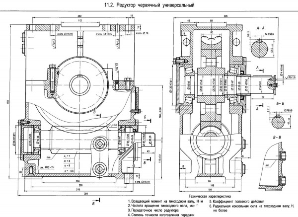
Universal worm gearbox
There are two possible options for assembling the housing of such a gearbox: with an upper or lower position of the worm relative to the worm wheel. The worm is threaded onto the input shaft, onto which angular contact tapered roller bearings are installed with tension. The input shaft is inserted through a hole in the housing. To adjust the bearings axially, sets of metal shims are provided under the input shaft support caps.
The gearbox housing has a connector along the axis of the output shaft, making it possible to install this shaft with a worm wheel and angular contact tapered bearings pre-fitted onto it with interference. To adjust the bearings and worm gear, a set of metal shims is provided under the worm wheel shaft support covers.
Geared motor with top-mounted worm
For assembly, a hole is provided in the solid gearbox housing, to which a flanged electric motor is attached through an adapter cup-cover. The electric motor shaft is connected to the input shaft of the gearbox by an elastic compensating coupling. The worm is threaded onto the input shaft, on which angular contact tapered roller bearings are pressed against each other. The “axial play” of the bearings is regulated by a set of metal spacers under the cover and under the cover cup of the input shaft supports. A worm wheel and roller angular contact tapered bearings are installed on the output shaft with an interference fit according to the design. The assembled output shaft is inserted into the housing through holes and covered with large side covers. To adjust the bearings and worm gear, there is a set of metal shims under the small covers of the worm wheel shaft supports.


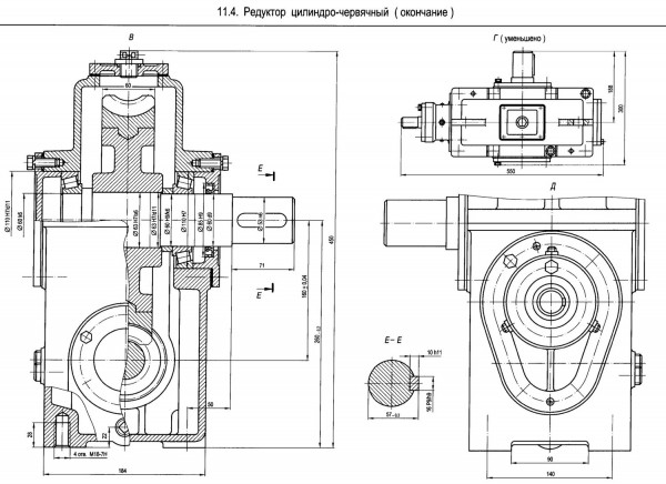
Helical-worm gearbox
The two-stage gearbox has a high-speed cylindrical and low-speed worm gear. The gearbox assembly sequence is as follows. An intermediate shaft is inserted through the hole in the housing, on which a worm is cut and the bearings of the right support, secured against axial displacement, are fitted with an interference fit. The support consists of two roller angular contact tapered bearings installed in the glass. Next, a spur gear wheel, a floating support for the intermediate shaft and a radial roller bearing with short rollers are put on the intermediate shaft. A high-speed gear shaft with a cut worm and tension-fitted radial ball bearings is pre-installed in a removable cover cup. Then, through a hole in the housing, it is engaged with cylindrical wheel the cantilever gear of the high-speed shaft and attach the lid cup to the body. The left shaft support is secured against axial movements with a ring and three set screws on one side and a cover on the other. The right shaft support is axially floating. A low-speed shaft with a worm wheel and roller angular contact tapered bearings mounted on it with an interference fit (they are positioned in the housing) is installed in the connector plane of the gearbox housing, passing along the axis of this shaft, and closed with a lid. Adjustment of first the bearings and then the worm gear is carried out with a set of metal spacers under the covers of the worm wheel shaft supports. To adjust the bearings of the fixed support of the intermediate shaft, use a set of metal shims under the cup cover.

Helical-worm gear motor
The two-stage gearbox has a high-speed cylindrical helical gear and low-speed worm. Assembly begins with the intermediate shaft, inserting it from left to right through the hole in the gearbox housing. A worm is cut on the intermediate shaft, and the bearings are tightly seated. The left support is fixed against axial displacement and consists of two roller angular contact tapered bearings installed in a glass and secured to the shaft with an end washer. This washer serves to transmit the axial force arising in the worm or gear engagement. The right shaft support, floating in the axial direction, is a radial ball bearing. It is installed in the intermediate partition of the gearbox housing. Then a high-speed gear is put on the intermediate shaft. cylindrical gear and secured with an end washer. The output shaft with a worm wheel and roller angular-contact tapered bearings mounted on it with interference (in the housing they are positioned in a counterarray) is placed in the plane of the housing connector, passing along the axis of this shaft, and is closed with a lid. Gear high speed transmission fixed on the shaft of a flanged electric motor, which is then attached to the side cover of the housing, and engaged with a cylindrical wheel.
To adjust the bearings and worm gearing, a set of metal shims is used, located under the covers of the worm wheel shaft supports. The fixed support bearings of the intermediate shaft are adjusted by a set of metal shims under the cup cover.
![]()

Two-stage worm gearbox
Assembly is carried out through holes in the one-piece gearbox housing. A worm wheel of a high-speed worm gear and bearings are mounted with an interference fit on an intermediate shaft with a cut worm. The right support is fixed against axial displacement and is a combination of two roller angular contact tapered bearings secured to the shaft with a nut and installed in a sleeve. The nut also serves to transmit axial forces. The left intermediate shaft support (radial roller bearing with short rollers) is axially floating. A high-speed shaft with a worm cut and tension-fitted angular contact roller bearings is inserted into the housing by surprise through a hole. To engage the worm with the high-speed wheel, the left shaft support has a cup, which is installed after the worm is engaged with the wheel. The output shaft of the gearbox with a low-speed worm wheel and bearings mounted on it with an interference fit is inserted through a hole in the housing and closed with a lid.
To adjust the staggered bearings and low-speed worm gearing, a set of metal spacers is used, located under the small covers of the output shaft supports. The tapered bearings of the intermediate shaft are adjusted by a set of metal shims under the cup cover, and the high-speed worm gear is adjusted by a set of metal shims under the flange of the intermediate shaft cup.