The minimum permissible modulus value can be determined based on bending. However, in most cases this results in gears with very fine teeth, the use of which is limited in practice.
Therefore, the values of the modulus m n are selected based on practical recommendations, and then the bending strength is checked:
For conventional gear type transmissions 
10.7. Calculation of gears under overloads.
This calculation is carried out only in case of planned overloads.
 ,
(9)
,
(9)
 ,
(10)
,
(10)
Here  And
And  - stresses during overload (T peak), respectively, contact and bending,
T peak – moment during overload,
T max – maximum long-term torque (determined from the load graph),
 And
And  - voltages determined at load Tmax,
 And
And  - permissible voltages during overload.
Since the load during overload acts for a short time, the values of the permissible voltages during overload are chosen to be high.
 - at T.O. – N., U., volumetric hardening,
 - with T.O. - carburization, high-frequency hardening, nitriding,
 - with NV
  ,
,
 - at HB>350.
10.8. The procedure for calculating cylindrical gears.
a) Closed transfers.
1. Having specified the material and technical characteristics, using formulas 2 or 6, based on contact strength, determine the interaxial distance a w;
2. Having set the coefficient  , determine the engagement modulus using the formula
 and other geometric parameters. In addition, the module must be within . The module must be of a standard size. In mechanical engineering m n
  .
.
3. Using formulas 1 or 5, the strength of the teeth is checked with specified geometric parameters.
4. Using formulas 3 or 7, the bending strength of the teeth is checked.
5. If necessary, the strength of the teeth under overloads is checked using formulas 9 and 10.
b) Open transfers.
1. Having specified the material and technical characteristics, the engagement modulus is determined using formulas 4 or 8 from the bending calculation. The value m n is a standard value.
2. Having specified the number of gear teeth z 1 = 20 – 25, the remaining geometric parameters are determined.
3. Using formulas 3 or 7, the bending strength of the teeth is checked with specified geometric parameters.
4. According to formula 10, if necessary, the strength of the teeth under overload is checked.
11. Bevel gears.
Refers to gears in which the shaft axes intersect at a certain angle  . The most common gears with an angle
  .
.
Bevel gears are more difficult to manufacture and install than cylindrical gears. To cut bevel wheels, special machines and special cutting tools are required (Glisson or Komsomolets type machines). In addition to tolerances on the size of the teeth, it is necessary to maintain tolerances on the angular dimensions, and during installation, ensure that the vertices of the pitch cones coincide. It is much more difficult to perform a conical engagement with the same degree of accuracy as a cylindrical engagement. The intersection of the shaft axes makes it difficult to place the supports. One of the bevel gears, as a rule, is placed in a cantilever position (usually a gear). This increases the uneven distribution of load along the length of the tooth. In the conical gearing, axial forces act, which complicate the design of the supports.
All this leads to the fact that, according to experimental data, the load capacity of a bevel spur gear is only about 0.85 cylindrical. Therefore, they are used only under the conditions of the arrangement of mechanisms, when it is necessary to position the shafts at an angle.
Gears are made of steel, cast iron and non-metallic materials. When choosing materials, it is necessary to ensure the bending strength of the teeth, the resistance of the surface layers of the teeth (contact strength) and resistance to jamming. The bearing capacity in terms of contact strength is proportional to the square of the hardness of the teeth, therefore, to increase the bearing capacity of the transmission and reduce dimensions, it is advisable to use steels that are hardened to significant hardness. However, high hardness reduces bending resistance, therefore, instead of volumetric hardening (where the entire volume of the gear material is hardened), surface thermal and chemical-thermal treatment (surface hardening of high-frequency high frequency, carburization, nitriding, etc.) is used, which impart high hardness to the surface of the teeth (for high contact strength) and retain a tough core (for high flexural strength).
During production steel gear wheels The following types of heat treatment are used:
Normalization makes it possible to obtain a hardness of 180...220 HB, therefore the load capacity is relatively small, but at the same time the wheel teeth are well run-in and retain the accuracy obtained with machining. Normalized wheels are usually used in auxiliary mechanisms, such as manual control mechanisms.
Steels used: 40, 45, 50, etc. To increase resistance to jamming, gears and wheels should be made of different materials.
Improvement allows you to obtain a surface and core hardness of 200...240 HB (for small gears 280...320 HB), the load capacity is slightly higher than with normalization, but the gear teeth are worn in worse. Typically, improved wheels are used in small-scale and single-piece production in the absence of strict requirements for dimensions.
Used steels: 40, 45, 50G, 35KhGS, 40Kh, etc.
Bulk hardening up to hardness 45…55 HRC. The entire volume of material is hardened (see above). Currently, it is almost not used, with the exception of repair enterprises where it is not possible to perform surface hardening.
Steels used: 40Х, in more critical cases – 40ХН, etc.
Surface hardening with heating by high frequency currents (HFC) to a hardness of 50...55 HRC with a depth of the hardened layer up to 3...4 mm - gives an average load capacity with a fairly simple hardening technology. The optimal calcination depth is 0.5…1 mm. HFC hardening is usually preceded by improvement, so the mechanical properties of the core are the same as during improvement.
The bending strength is 1.5-2 times higher compared to volumetric hardening. Due to the increased hardness of the teeth, gears do not break in well. The sizes of gears are practically unlimited. It must be remembered that with modules less than 3...5 mm, the tooth is calcined through and through, which leads to significant warping and a decrease in impact strength.
Used steels: 40Х, 40ХН, 35ХМ, 35ХГСА.
Cementation(surface saturation with carbon) followed by high-frequency hardening and mandatory grinding makes it possible to obtain a surface hardness of 56...63 HRC with a depth of the hardened layer of 0.5...2 mm. The load capacity is high, but the hardening technology is more complex. The bending strength is 2-2.5 times higher compared to volumetric hardening.
Steel 20Х is widely used, and for critical gears, especially those working with overloads and shock loads, steel 12ХН3А, 20ХНМ, 18ХГТ, 25ХГМ, 15ХФ.
Nitriding(surface saturation with nitrogen) provides high hardness and wear resistance of surface layers with a depth of the hardened layer of 0.2...0.5 mm, and does not require subsequent hardening and grinding. The small thickness of the hardened layer does not allow the use of nitrided wheels under shock loads and when working with intense wear (dirty lubricant, abrasive contact). The duration of the nitriding process reaches 40-60 hours. Typically, nitriding is used for internal gear wheels and others that are difficult to grind.
Molybdenum steel 38Kh2MYuA is used, but nitriding of steels 40KhFA, 40KhNA, 40Kh is possible to lower hardness but higher toughness.
Nitrocarburization– saturation of surface layers with carbon and nitrogen in gas environment with subsequent hardening provides high contact strength, wear resistance and resistance to jamming, and has a fairly high process speed - about 0.1 mm/hour and higher. Due to the low warpage, it allows in many cases to do without grinding. The nitrogen content in the surface layer allows the use of less alloyed steels than during carburization: 18KhGT, 25KhGT, 40Kh, etc.
Laser hardening– provides high hardness up to 64 HRC, does not require alloying, allows local hardening, automation, does not cause warping, but the process is very slow.
Cast iron gear wheels cheaper than steel ones, they are used in large-sized open transmissions. They have a low tendency to seize and perform well in poor lubrication conditions, but do not withstand shock loads. Gray cast iron SCh 20...SCh 35 is used, as well as high-strength magnesium cast iron with nodular graphite.
Wheels made of non-metallic materials have a small weight, are not subject to corrosion, and are silent in operation. But low strength, large dimensions, and tendency to aging limit their use in power transmissions. Typically, plastic gears are used in conjunction with a steel gear in lightly loaded transmissions to ensure quietness, or self-lubrication, or chemical resistance. In this case, it is advisable to harden steel wheels to 45 HRC and grind them. Long-used plastics include textolite grades PT and PTK and wood-laminated plastics DSP-G. The most promising are caprolon, polyformaldehyde and phenylone.
The material of gear wheels is selected depending on the purpose and operating conditions of the latter, the loads they transmit, rotation speeds, etc. When choosing a steel grade, it is necessary to take into account the following requirements: low cost of material, good machinability, minimal warping during hardening and three main performance indicators - high strength, long service life and increased wear resistance.
For most gears combines, tractors, cars and other agricultural machines that transmit large loads, the limiting factors are: tooth strength - bending resistance, resistance of the tooth profile surface against fatigue failure (pitting) and tooth wear. One of these factors may limit it, but then all three factors have almost the same values.
The following steels are most widely used for the production of gears:
carbon - 40, 50, 45;
chromium – 20Х, 35Х, 40Х, 50Х;
chromium-nickel – 12ХН3А, 12Х2Н4А, 20ХН;
chromium-manganese – 18ХГ, 18ХГТ, 25ХГТ, 30ХГТ;
chrome-molybdenum – 20ХМ, 30ХМ.
In addition, cast steel wheels are made from carbon steel 40L, 50L, and gear wheels of light-loaded transmissions of agricultural machines are made from SCh18 cast iron. For light loads, gears can also be made from textolite, nylon and other non-metallic materials.
It is known that to increase strength and wear resistance, one or more alloying elements are added to steel. Chromium is one of the most versatile and widely used alloying elements. Chromium enhances the effect of carbon, increases hardness, wear resistance and hardenability when heat treatment. Nickel increases impact strength, elastic limit and tensile strength of steel . The tough and tough surface of nickel steels provides high resistance to fatigue and wear. Nickel steels are easily carburized; nickel reduces deformation and provides good properties cores. Manganese increases strength, wear resistance, and depth of hardenability. Molybdenum increases the hardenability of steels at tempering temperatures.
Alloy steels containing chromium, nickel, molybdenum, and manganese are used for the manufacture of highly loaded gears. The best properties in the finished gear are obtained after carburizing. The carbon content of case-hardened steels typically ranges from 0.15 to 0.25%. Low carbon steels provide maximum tooth toughness, while high carbon steels provide maximum core strength. The depth of the cemented layer of gears is 1…2 mm.
Chromium-nickel, chromium-manganese and chromium-molybdenum steels are widely used in the manufacture of automobile gears.
Materials for the manufacture of gears in mechanical engineering - steel, cast iron and plastics; in instrument making, gears are also made of brass, aluminum alloys, etc. The choice of material is determined by the purpose of the gear, its operating conditions, the dimensions of the wheels and even the type of production (single, serial or mass) and technological considerations.
General modern trend in mechanical engineering - the desire to reduce the material consumption of structures, increase the power, speed and durability of the machine. These requirements lead to the need to reduce the weight, dimensions and increase the load capacity of power gears. That's why basic materials for the manufacture of gears - heat-treated carbon and alloy steels, providing high volumetric strength of the teeth, as well as high hardness and wear resistance of their active surfaces.
Depending on the hardness of the active tooth surfaces, steel wheels are divided into two groups, namely: wheels with hardness N ≤ 350 HB, the teeth of which are well worn in; wheels with hardness N≥ 350 HB, the teeth of which are poorly worn in, and with the hardness of the active surfaces of both wheels N ≥ HRCs are considered not to be used.
In addition to the ability to run-in, these groups differ in machining technology, as well as in load capacity.
Wheels of the first group, made from medium and high carbon steels, are subjected to normalization or improvement; Finish cutting of teeth is carried out after heat treatment, and finishing operations are not required. These technological advantages of wheels of the first group ensure their widespread use in single or small-scale production of light and medium-loaded gears, as well as gears with large wheels.
Wheels of the second group are made of alloy steels subjected to various types thermal and chemical-thermal treatment (cementation, volumetric or surface hardening, nitriding, planning, nitrocarburization), and are used for high-speed and highly loaded gears.
The teeth of the wheels of the second group are cut before heat treatment, which causes warping of the teeth and a decrease in the accuracy of the ring gear. To correct the shape of the teeth, expensive finishing operations are required (grinding, rolling, lapping of teeth, etc.), therefore wheels with high-hardness teeth are used in products of large-scale and mass production. All other things being equal, the mass of the wheels of the second group is 3–4 times less than that of the first.
For the manufacture of low-speed, predominantly open gears operating at peripheral speeds of up to 3 m/s, gray, modified and high-strength cast irons are used, which have good casting properties, low cost with minimal waste of material into chips.
Load capacity of gear wheels made of non-metallic materials are significantly lower than steel ones, so they are used in lightly loaded gears, the dimensions of which are not subject to strict conditions, but noise and vibration reduction, self-lubrication or chemical resistance are required. Gears made of non-metallic materials are most often used in conjunction with metal ones. For the manufacture of non-metallic wheels, textolite, wood-laminated plastics, nylon, nylon, etc. are used.
When selecting materials and assigning their heat treatment, it is necessary to take into account that the gear tooth in And(gear ratio) times more often engages than a wheel tooth. Therefore, for steel wheels of the first group, in order to equalize durability and improve wearability, the hardness of the active surfaces of the gear teeth should be made greater than that of the wheel, and it is recommended to have
N 1sr – N 2sr ≥ 20.
For the manufacture of gears and wheels of the first group, it is advisable to use steel of the same grade, and ensure the difference in hardness through heat treatment.
For wheels with non-running teeth, it is not necessary to ensure a difference in the hardness of the gear teeth and the wheel.
Spur wheel design depends on their material, size and manufacturing method.
Steel Gear wheels with a diameter of up to 150 mm (Fig. 1.62) are made from rods or forgings and are made in the form of solid disks with double-sided ( A), one-sided ( b) with or without a hub ( V).Steel wheels with a diameter of up to 500 mm are most often made forged or stamped; they have a rim and a hub connected by a disk with holes (Fig. 1.62, G). Gears whose diameter is less than twice the diameter of the shaft are manufactured as one piece with the shaft and are called pinion shaft(Fig. 1.62, d). Gearboxes use several gears made from one piece of metal; such gears are called gear blocks. Wheels with a diameter of more than 500 mm are usually made by casting; the rim and hubs are connected by cross-shaped spokes (Fig. 1.63, A), oval, T-shaped and other sections. In a single production wheel large diameter make a welded structure (Fig. 1.63, b). In order to save high quality steel wheels large diameters often made with bandages (Fig. 1.63, V), when a steel rim is pushed onto a cast iron center; designs are also used in which the rim and center are connected with fastening bolts.
Rice. 1.62. Types of steel gears
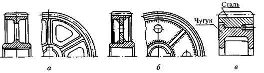
Rice. 1.63. Options for manufacturing large diameter gears
Cast iron Gear wheels, regardless of their size, are manufactured by casting followed by machining.
Non-metallic Gear wheels are made in one piece or in parts. Figure 1.64 shows a composite gear made of glued PCB plates, placed on a metal sleeve and fastened with discs using bolts. Gears made of nylon and nylon are made by injection molding; Often a crown made of these materials is cast together with a steel center or is pressed onto the center and fastened with screws.

Rice. 1.64. Non-metallic gear manufacturing option
Teeth Formation Methods can be divided into two main groups: rolling and cutting (in addition, wheels with cast teeth are sometimes made).
Rolling of teeth steel wheels are produced using a rolling tool through plastic deformation of the wheel crown. Rolling of teeth with a modulus of up to 1 mm is carried out in a cold state; with a larger module, the crown is heated by high-frequency currents.
Gear rolling is used in mass production and is a high-performance method that ensures minimal metal waste into chips and increases the strength of the teeth, since the metal fibers in the workpiece are not cut, but bent.
Tooth cutting performed by the copying method and the running-in method.
Copy method consists in the fact that the cavities of the ring gear are cut by a tool whose cutting part profile exactly or approximately matches the outlines of the cavities. Figure 1.65 shows tooth milling cylindrical wheel modular cutters: disk ( A) and terminal ( b).After cutting one cavity, the workpiece returns to its original position, rotates by the amount of the angular step, and the process is repeated.


Rice. 1.65. Milling spur gear teeth
Since the shape of the cavity changes with the change in the number of teeth of the wheel, for each module and number of teeth you need to have your own cutter, which is practically impossible. Therefore, with a milling cutter of one module, depressions are cut in a certain range of tooth numbers (for example, with a milling cutter for 30 teeth, wheels with a number of teeth from 24 to 36 are processed), as a result of which the teeth will not always have an accurate profile. Milling teeth using the copying method is a simple, but not accurate enough and very low-productivity method, used mainly in single production.
The copying method includes methods of forming wheel teeth by broaching, cold or hot stamping, as well as pressing and injection molding.
Run-in method(bending) is a highly accurate, high-performance, universal and most common method of forming teeth. The previously discussed process of rolling teeth can be classified as the rolling method.
The process of cutting teeth on gear-processing machines is likened to the process of engaging a pair of gear wheels or a wheel with a rack, when one of the wheels or the rack is equipped with cutting elements and is thus transformed into a cutting tool called producing wheel. The gearing of the producing wheel with the gear being processed is called machine gearing. Figure 1.66 shows the main types of machine gears and the corresponding movements of the tool and workpiece: A - cutting teeth with a tool rack (gear cutting comb) on a gear shaping machine; b – cutting teeth with a gear cutter on a gear shaping machine; V - cutting teeth with a modular hob cutter on a gear hobbing machine (the modular hob cutter has the profile of a tool rack in its axial section).
The gear cutting tool is profiled based on standard initial contours, one of which (for cylindrical involute gears with modules greater than 1 mm) is shown in Fig. 1.57. The same tool can be used to cut wheels of a given module with different numbers of teeth, which is a very significant advantage of the running-in method. On gear shaping machines, wheels with both external and internal teeth are processed with a shaper. Using hob cutters on gear hobbing machines, you can cut spur, helical and herringbone wheels with a track in the middle (for exit cutting tool); chevron wheels without a track are cut with special helical cutters or combs. The most productive method of cutting teeth is hob milling. As a rule, gear cutting machines are semi-automatic.
If it is necessary to obtain very precise and clean tooth surfaces, finishing operations are used: shaving, rolling (for teeth of low hardness) or grinding, lapping (for hardened teeth).
Offset gears . The need to reduce the material consumption of structures and obtain minimum dimensions leads to the need to create gears with the lowest possible number of teeth. However, when cutting gears with a small number of teeth in the machine gearing, the phenomenon occurs tooth interference, when part of the space is simultaneously occupied by the teeth of the producing and processed wheels.
Interference leads to cutting off part of the nominal surface at the base of the tooth of the wheel being processed ( cutting teeth) or cutting off part of the nominal surface at the top of the tooth ( cutting teeth, characteristic of wheels with internal teeth).

Rice. 1.66. Main types of machine gears
In Fig. 1.67, A shows the change in tooth shape depending on the number of teeth of the wheel.

Rice. 1.67. Schemes for changing the tooth shape and shifting the tool rack in the machine gearing
As the number of teeth decreases, their thickness at the base decreases, the tooth becomes sharper at the tip, and the curvature of the involute profile increases - all this leads to a decrease in the strength of the tooth. When the number of teeth is less than z min, the phenomenon of interference occurs in the machine gearing, and cutting of the teeth occurs. In order to avoid cutting teeth in the machine gearing, the tool rack is shifted by the amount xt, Where X - displacement coefficient; T - tooth module (Fig. 1.67, b).
The displacement of the rack from the wheel axis is considered positive, and towards the axis - negative. The figure shows the limit position of the rack at which cutting of the teeth stops, i.e. position when line AB the top of the tool rack (the shaded rounded part of the rack does not participate in the formation of the active tooth profile) will pass through the point IN on the engagement line. Since the tool tooth dimensions are standardized, other things being equal, the risk of undercutting is determined by the number of gear teeth.
When choosing materials, it is necessary to ensure the bending strength of the teeth, the resistance of the surface layers of the teeth (contact strength) and resistance to jamming. The bearing capacity in terms of contact strength is proportional to the square of the hardness of the teeth, therefore, to increase the bearing capacity of the transmission and reduce dimensions, it is advisable to use steels that are hardened to significant hardness. However, high hardness reduces bending resistance, therefore, instead of volumetric hardening (where the entire volume of the gear material is hardened), surface thermal and chemical-thermal treatment (surface hardening of high-frequency high frequency, carburization, nitriding, etc.) is used, which impart high hardness to the surface of the teeth (for high contact strength) and retain a tough core (for high flexural strength).
During production steel gears The following types of heat treatment are used:
· Normalization allows you to obtain a hardness of 180...220...
HB, therefore the load capacity is relatively small, but at the same time the wheel teeth are well run-in and maintain the accuracy obtained during machining. Normalized wheels are usually used in auxiliary mechanisms, such as manual control mechanisms.
Steels used: 40, 45, 50, etc. To increase resistance to jamming, gears and wheels should be made of different materials.
· Improvement allows you to obtain a surface and core hardness of 200...240 HB (for small gears 280...320 HB), the load capacity is slightly higher than with normalization, but the gear teeth are worn in worse. Typically, improved wheels are used in small-scale and single-piece production in the absence of strict requirements for dimensions.
Used steels: 40, 45, 50G, 35KhGS, 40Kh, etc.
· Bulk hardening up to hardness 45…55 HRC. The entire volume of material is hardened (see above). Currently, it is almost not used, with the exception of repair enterprises where it is not possible to perform surface hardening.
Steels used: 40Х, in more critical cases – 40ХН, etc.
· Surface hardening with heating by high frequency currents (HFC) to a hardness of 50...55 HRC with a depth of the hardened layer up to 3...4 mm - gives an average load capacity with a fairly simple hardening technology. The optimal calcination depth is 0.5…1 mm. HFC hardening is usually preceded by improvement, so the mechanical properties of the core are the same as during improvement.
The bending strength is 1.5-2 times higher compared to volumetric hardening. Due to the increased hardness of the teeth, gears do not break in well. The sizes of gears are practically unlimited. It must be remembered that with modules less than 3...5 mm, the tooth is calcined through and through, which leads to significant warping and a decrease in impact strength.
Used steels: 40Х, 40ХН, 35ХМ, 35ХГСА.
· Cementation(surface saturation with carbon) followed by high-frequency hardening and mandatory grinding makes it possible to obtain a surface hardness of 56...63 HRC with a depth of the hardened layer of 0.5...2 mm. The load capacity is high, but the hardening technology is more complex. The bending strength is 2-2.5 times higher compared to volumetric hardening.
Steel 20Х is widely used, and for critical gears, especially those working with overloads and shock loads, steel 12ХН3А, 20ХНМ, 18ХГТ, 25ХГМ, 15ХФ.
· Nitriding(surface saturation with nitrogen) provides high hardness and wear resistance of surface layers with a depth of the hardened layer of 0.2...0.5 mm, and does not require subsequent hardening and grinding. The small thickness of the hardened layer does not allow the use of nitrided wheels under shock loads and when working with intense wear (dirty lubricant, abrasive contact). The duration of the nitriding process reaches 40-60 hours. Typically, nitriding is used for internal gear wheels and others that are difficult to grind.
Molybdenum steel 38Kh2MYuA is used, but nitriding of steels 40KhFA, 40KhNA, 40Kh is possible to lower hardness but higher toughness.
· Nitrocarburization– saturation of surface layers with carbon and nitrogen in a gaseous environment followed by hardening provides high contact strength, wear resistance and resistance to seizing, and has a fairly high process speed - about 0.1 mm/hour and higher. Due to the low warpage, it allows in many cases to do without grinding. The nitrogen content in the surface layer allows the use of less alloyed steels than during carburization: 18KhGT, 25KhGT, 40Kh, etc.
· Laser hardening– provides high hardness up to 64 HRC, does not require alloying, allows local hardening, does not cause warping, is well automated, but the process is very slow.
Characteristics mechanical properties common steels used for the manufacture of gears, after thermal or thermochemical treatment are presented in table. 2.2.
Obtaining the desired mechanical properties depends not only on temperature regime heat treatment, but also from largest sizes workpiece sections D or wheel thickness (Fig. 2.11).
During surface heat treatment of teeth, the mechanical characteristics of the tooth core depend on the previous operation - improvement. The exception is teeth with m < 3 мм, подвергаемые закалке ТВЧ: они прокаливаются насквозь, что приводит к значительному их короблению и снижению ударной вязкости.
Cast iron gears Cheaper than steel ones, they are used in large-sized open gears. They have a low tendency to seize and perform well in poor lubrication conditions, but do not withstand shock loads. Gray cast iron SCh 20...SCh 35 is used, as well as high-strength magnesium cast iron with nodular graphite.
Wheels made of non-metallic materials have a small weight, are not subject to corrosion, and are silent in operation. But low strength, large dimensions, and tendency to aging limit their use in power transmissions. Typically, plastic gears are used in conjunction with a steel gear in lightly loaded transmissions to ensure quietness, or self-lubrication, or chemical resistance. In this case, it is advisable to harden steel wheels to 45 HRC and grind them. Long-used plastics include textolite grades PT and PTK and wood-laminated plastics DSP-G. The most promising are caprolon, polyformaldehyde and phenylone.