MARKING STAIRS, PLATFORMINGS AND STEEL FENCES
Specifications
Steel flights of steps, stair landings and railings. Specifications
Date of introduction 1979-01-01
INFORMATION DATA
1. DEVELOPED AND INTRODUCED to the Order of the Red Banner of Labor by the Central Research and Design Institute of Building Metal Structures (TsNIIproektstalkonstruktsiya) of the USSR State Construction Committee
All-Union Scientific Research and Design-Technological Institute (VNIKTIstalkonstruktsiya) Ministry of Installation and Special Construction of the USSR
All-Union State Design Institute for Industrialization installation work(Gipromontazhindustriya) Ministry of Montazhspetsstroy USSR
DEVELOPERS: V.M. Laptev (topic leader), L.A. Peskova, S.I. Bochkova, A.F. Gai, L.M. Dudilovsky, B.A. Shtepa
2. APPROVED AND ENTERED INTO EFFECT by the Resolution State Committee Council of Ministers of the USSR for Construction Affairs dated April 28, 1978 No. 71
3. INTRODUCED FOR THE FIRST TIME
4. REFERENCE REGULATIVE AND TECHNICAL DOCUMENTS
5. REPUBLICATION. May 1992
6. By Decree of the USSR State Committee for Construction Affairs No. 354 dated February 29, 1984, the validity period was lifted
This standard applies to steel marching stairs, platforms and fences for them, used in industrial buildings and structures erected and operated in areas with a design temperature of minus 65°C and above.
The standard sets technical requirements for flight stairs with an inclination angle of 45 and 60°, rectangular transition platforms and fences for them, made of cold-formed and hot-rolled profiles and designed for standard temporary loads of 200, 300 and 400 kgf/cm2.
Flight stairs, platforms and fences for them must meet all the requirements of GOST 23118 and the requirements set out in the relevant sections of this standard.
1. Main parameters and dimensions
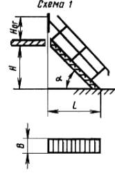
1.1. Main parameters and dimensions flights of stairs, rectangular platforms and fences for them must correspond to those indicated in Figures 1-4 and in Tables 1-4.
An example of a symbol for a brand of flight of stairs (ML) made of a cold-formed profile (X) with stamped steps (W), at an angle of 45° and dimensions H = 6 dm and H = 8 dm: MLKhSh45-6.8 GOST 23120-78
The same, platforms (PM) made of cold-formed profile with corrugated flooring (F) and dimensions Lp = 9 dm and B = 6 dm: PMHF-9.6 GOST 23120-78
The same, the left railing (OGl) of a flight of stairs from a cold-formed profile without a side element, at an angle of 45° and dimensions Leg = 10 dm and H = 24 dm: OGlMLH45-10.24 GOST 23120-78
The same, right guardrail (OGp) with side element (Eb): OGpMLHEb45-10.24 GOST 23120-78
The same, platform fencing made of cold-formed profile with side element and dimensions Leg = 10 dm and Log = 9 dm: OGPMKHEb-10.9 GOST 23120-78
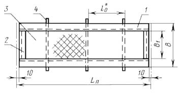
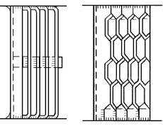
Flight of stairs
1 - stringer; 2 - stage; 3 - support bar; 4 - support corner; 5 - rib.
Damn.1
Venues

1 - beam; 2 - edging element; 3 - flooring; 4 - rib.
Damn.2
*According to KMD drawings.
1.2. Depending on the operating conditions, the steps of flight stairs and decking of rectangular platforms should be made of two types:
1 - solid made of corrugated steel (F);
2 - lattice, versions:
Ш - from stamped elements;
R - from strips on the edge and round steel;
C - from stripes on an edge in one direction;
B - made of expanded steel.
1.3. The types of steps of flight stairs and floorings in rectangular platforms are shown in Figure 5.
1.4. Layout diagrams of flight stairs, platforms and fences are given in the appendix.
Table 1 (dimensions in mm)
| a | H | L | h | b | B | B1 | b1 |
| 600 | 600 | ||||||
| 1200 | 1200 | ||||||
| 45º | 1800 | 1800 | 600 | 500 | 7 | ||
| 2400 | 2400 | 200 | 200 | 800 | 700 | 10 | |
| 3000 | 3000 | 1000 | 900 | ||||
| 3600 | 3600 | ||||||
| 4200 | 4200 | ||||||
| 600 | 345 | ||||||
| 1200 | 693 | ||||||
| 1800 | 1039 | ||||||
| 2400 | 1386 | 600 | 500 | ||||
| 60º | 3000 | 1732 | 300 | 200 | 5 | ||
| 3600 | 2078 | 800 | 700 | ||||
| 4200 | 2425 | ||||||
| 4800 | 2771 | ||||||
| 5400 | 3118 | ||||||
| 6000 | 3464 |
Table 2 (dimensions in mm)
| Ln | 900; 1200; 1500; 1800; 2100; 2400; 3000; 3600; 4200; 4800; 5400; 6000 |
| B | 600; 800; 1000 |
| B1 | 500; 700; 900 |
2. Technical requirements
2.1. The structures of flights of stairs, landings and fences to them (hereinafter referred to as the structures) should be manufactured in accordance with the requirements of this standard, SNiP III-18 according to the working drawings of KMD, approved in the prescribed manner.
2.2. Structures should be made of carbon steel class C38/23 of the following grades in accordance with GOST 380:
St3kp - for construction areas with an estimated outside air temperature of minus 40°C and above;
St3Gps - the same, with an estimated outside air temperature below minus 40 to minus 65°C inclusive.
2.3. Limit deviations linear dimensions structures from the nominal ones, deviations of the shape and arrangement of surfaces from the design ones are given in Table 5.
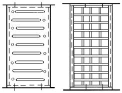
Types of steps of flight stairs and decking platforms
Type 1. Solid (F)

Type 2. Lattice
Execution Ш Execution R

Execution C Execution B

2.6. For bolted connections Bolts of normal accuracy must be used in accordance with GOST 7798 and in accordance with SNiP II-B.3.
2.7. Structures must be primed and painted. Primer and painting must comply with coating class V according to GOST 9.032.
2.8. Factory and installation joints of fencing elements should not have sharp protrusions or edges.
Table 5 (dimensions in mm)
| Nominal size and name of deviation | Prev. off flight of stairs, landing, fencing of flight of stairs and landing | Sketch |
| 1. Length Lк; Ln; Log up to 1000 incl. | ||
| 2. Width B1 St. 1000 to 1600 incl. | ||
| 3. Height Hp; Hl: St. 1600 to 2500 incl. " 2500 " 4000 " " 4000 " 8000 " |
± 2.5 ± 3.0 ± 4.0 |
|
| 4. The distance between the ribs in the stringers and beams of the platforms lo | ± 2.0 | Drawings 1 and 2 |
| 5. Distance between fence posts lo | ± 2.0 | Drawings 3 and 4 |
| 6. Inequality of diagonals (non-rectangularity), no more | 4,0 | |
| 7. Distance between the centers of holes within one group A | ± 1.3 | |
| 8. Distance between groups of holes A | ± 2.5 |  |
| 9. Deviation from straightness (δ) along length L: up to 1000 incl. St. 1000 to 1600 incl. " 1000 " 2500 " " 2500 " 4000 " " 4000 " 8000 " |
0,8 1,3 2,0 3,0 5,0 |
 |
3. Completeness
3.1. The structures must be supplied by the manufacturer in a comprehensive manner.
The kit should include:
flights of stairs, landings and fences to them;
additional parts for connecting structures;
bolts, nuts and washers (supplied in quantities 10% more than specified in the design drawings);
technical documentation in accordance with the requirements of GOST 23118.
4. Acceptance rules
4.1. Designs to verify compliance with the requirements of this standard must be accepted by the technical control of the manufacturer.
4.2. Control of deviations of linear dimensions of structures (including cross-sectional dimensions of rolled profiles) from nominal, deviations of the shape and location of surfaces of parts from design, quality welded joints and surface preparation for protective coatings must be carried out before priming the structures.
4.3. Acceptance of structures must be carried out in batches. The batch includes similar structures, manufactured using the same technology, from materials of the same quality.
The batch size is established by agreement between the manufacturer and the consumer.
4.4. During random acceptance inspection, 3 designs are selected from the batch. must be subjected to piece-by-piece inspection for compliance with the requirements established by this standard.
4.5. If, when checking the selected structures, there is at least one structure that does not meet the requirements of this standard, a double number of structures from the same batch should be selected and re-tested. If, upon re-inspection, there is at least one design that does not meet the requirements of this standard for one of the indicators, then this batch is rejected and sent for revision.
4.6. The consumer has the right to accept structures, applying the acceptance rules and control methods established by this standard.
5. Control methods
5.1. Monitoring of deviations of the linear dimensions of structures from nominal, deviations of the shape and location of surfaces from the design ones should be carried out universal methods and means.
5.2. Quality control of seams of welded joints and the dimensions of their sections must be carried out in accordance with SNiP III-18.
6. Labeling, packaging, transportation and storage
6.1. Manufactured structures must be marked.
6.2. The structures of staircases and landings must be transported element by element or in packages consisting of several elements. Fencing structures should only be transported in packages.
6.3. The method of connecting structural elements into packages must prevent their mutual displacement and damage during transportation and storage.
6.4. A tag is attached to each package or structure, on which the following markings must be applied: order number; number of the KMD drawing according to which the structure was made.
6.5. Each structural element must be marked symbol brand of the element (without standard designation, see clause 1.1).
6.6. Markings must be applied with indelible paint on the wall of the stringer of the flight of stairs on the right side along the ascent, on the wall of the landing beam and on the upper edge of the handrail of the fence.
6.7. Connecting parts of structures must be supplied along with the structures. By agreement with the customer, it is possible to supply connecting parts separately from structures, in which case they must be packaged in wooden boxes according to GOST 2991.
6.8. The weight of the package should not exceed 3 tons.
6.9. Structures must be transported and stored in stacks in a horizontal position supported on wooden pads and gaskets. The pads must be at least 50 mm thick and at least 100 mm wide. Gaskets must be at least 20 mm thick and at least 100 mm wide.
The height of the stack should be no more than 1.5 m for fences and 2.0 m for marches and platforms.
7. Installation instructions
7.1. Installation of structures must be carried out in accordance with the requirements of GOST 23118 and SNiP III-18.
7.2. The installation of structures must ensure their design position, which excludes the formation of a reverse slope of the steps of more than 1°.
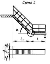
H, L, B, Lп, Hog - nominal dimensions of staircase elements;
α - angle of inclination of stairs; b - step width; h - step height.
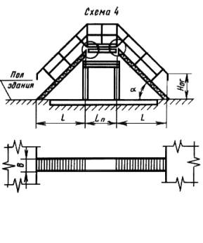
In diagrams 2-5, the nodes circled are made rigid by welding with the help of additional elements.
The text of the document is verified according to: official publication of the Ministry of Construction of Russia - M.: Standards Publishing House, 1992
STATE STANDARD OF THE USSR UNION
MARCHING STAIRS,
SITES AND FENCES
STEEL
TECHNICAL CONDITIONS
GOST 23120-78
STATE COMMITTEE OF THE USSR
ON CONSTRUCTION AFFAIRS
Moscow
DEVELOPED AND INTRODUCED to the Order of the Red Banner of Labor by the Central Research and Design Institute of Building Metal Structures (TsNIIproektstalkonstruktsiya) of the USSR State Construction Committee
All-Union Scientific Research and Design-Technological Institute (VNIKTIstalkonstruktsiya) Ministry of Installation and Special Construction of the USSR
All-Union State Design Institute for Industrialization of Installation Works (Gipromontazhindustriya) Ministry of Montazhspetsstroy USSR
PERFORMERS
V. M. Laptev(topic leader), L. A. Peskova, S. I. Bochkova, A. F. Gai, L. M. Dudilovsky, B. A. Shtepa
APPROVED AND ENTERED INTO EFFECT by Resolution of the State Committee of the Council of Ministers of the USSR for Construction Affairs dated April 28, 1978 No. 71
STATE STANDARD OF THE USSR UNION
By Resolution of the State Committee of the USSR Council of Ministers for Construction Affairs dated April 28, 1978 No. 71, the validity period was established
from 01/01/1979
until 01/01/1984
This standard applies to steel flight stairs, platforms and their fencing used in industrial buildings and structures constructed and operated in areas with a design temperature of minus 65 °C and above.
The standard establishes technical requirements for flight stairs with an inclination angle of 45 and 60°, rectangular transition platforms and fences for them, made of cold-formed and hot-rolled profiles and designed for standard temporary loads of 200, 300 and 400 kgf/m 2.
Flight stairs, platforms and fences for them must meet all the requirements of GOST 23118-78 and the requirements set out in the relevant sections of this standard.
1. Main parameters and dimensions
1.1. The main parameters and dimensions of flights of stairs, rectangular platforms and fences to them must correspond to those indicated in the drawing. 1 - 4 and in table. 14 .
Flight of stairs

____________
*According to KMD drawings.
1 - kosour; 2 - step; 3 - support bar; 4 - support corner; 5 - rib
Crap. 1
Table 1
Dimensions in mm
|
a |
H |
L |
h |
b |
B |
B 1 |
B 1 |
|
45° |
|||||||
|
1200 |
1200 |
||||||
|
1800 |
1800 |
||||||
|
2400 |
2400 |
||||||
|
3000 |
3000 |
1000 |
|||||
|
3600 |
3600 |
||||||
|
4200 |
4200 |
||||||
|
60° |
|||||||
|
1200 |
|||||||
|
1800 |
1039 |
||||||
|
2400 |
1386 |
||||||
|
3000 |
1732 |
||||||
|
3600 |
2078 |
||||||
|
4200 |
2425 |
||||||
|
4800 |
2771 |
||||||
|
5400 |
3118 |
||||||
|
6000 |
3464 |
Venues
______________
*According to KMD drawings.
1 - beam; 2 - edging element; 3 - flooring; 4 - rib
Crap. 2
Table 2
mm
|
Ln |
900; 1200; 1500; 1800; 2100; 2400; 3000; 3600; 4200; 4800; 5400; 6000 |
|
B |
|
|
B 1 |
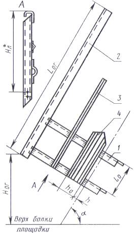
Stair railing
____________
*According to KMD drawings.
1 - stand; 2 - handrail, 3 4 - side element
Crap. 3
Table 3
Dimensions in mm
|
a |
H or |
L or |
h o |
h |
l o |
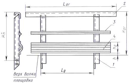
Site fencing
____________
*According to KMD drawings.
1 - stand; 2 - handrail, 3 - middle enclosing element; 4 - side element
Crap. 4
Table 4
mm
|
H or |
1000; 1200 |
|
L or |
900; 1200; 1500; 1800; 2100; 2400; 3000; 3600; 4200; 4800; 5400; 6000 |
|
h o |
140 |
|
h |
|
|
l o |
From 600 to 1300 |
Example of a symbolbrand of flight of stairs (ML) from a cold-formed profile (X) with stamped steps (W), at an angle of 45° and dimensions N= 6 dm and IN= 8 dm:
MLKhSh45-6.8 GOST 23120-78
The same, platforms (PM) made of cold-formed profile with corrugated flooring (F) and dimensionsLn= 9 dm and IN= 6 dm:
PMHF-9.6 GOST 23120-78
The same, the left railing (OGl) of a flight of stairs from a cold-formed profile without a side element, at an angle of 45° and dimensionsH or= 10 dm and H= 24 dm:
OGlMLH45-10.24 GOST 23120-78
The same, right guardrail (OGp) with side element (EB):
OGpMLHEb45-10.24 GOST 23120-78
The same, platform fencing made of cold-formed profile with side element and dimensionsH or= 10 dm and L or= 9 dm:
OGPMHEb-10.9 GOST 23120-78
1.2. Depending on the operating conditions, the steps of flight stairs and decking of rectangular platforms should be made of two types:
1 - solid made of corrugated steel (F);
2 - lattice, versions:
Ш - from stamped elements;
R - from strips on the edge and round steel;
C - from stripes on an edge in one direction;
B - made of expanded steel.
1.3. The types of steps of flight stairs and floorings in rectangular platforms are shown in Fig. 5 .
1.4. Layout diagrams of flight stairs, platforms and fences are given in the appendix.
Types of steps of flight stairs and decking platforms
Type 1. Solid (F)

Type 2. Lattice
Execution Ш Execution R
Execution C Execution B
Crap. 5
2. Technical requirements
2.1. The structures of flights of stairs, landings and fences to them (hereinafter referred to as the structures) should be manufactured in accordance with the requirements of this standard, SNiP III-18-75 according to the working drawings of KMD, approved in the prescribed manner.
2.2. Structures should be made of carbon steel class C38/23 of the following grades in accordance with GOST 380-71:
VSt3kp2 - for construction areas with an estimated outside air temperature of minus 40 °C and above;
VSt3Gps5 - the same, with an estimated outside air temperature below minus 40° From up to minus 65 °C incl.
2.3. The maximum deviations of the linear dimensions of structures from the nominal ones, deviations of the shape and location of surfaces from the design ones are given in Table. 5 .
2.4. Welded connections of elements must be performed mechanized. It is allowed, in the absence of equipment for welding by mechanized methods, to use manual welding.
2.5. Materials for welding must be accepted in accordance with SNiP II -B.3-72.
2.6. For bolted connections, bolts of normal accuracy must be used in accordance with GOST 7798-70 and in accordance with SNiP II -B.3-72.
2.7. Structures must be primed and painted. The primer and painting must correspond to the fifth class of coating according to GOST 9.032-74.
2.8. Factory and installation joints of fencing elements should not have sharp protrusions or edges.
Table 5
mm
|
Nominal size and name of deviation |
Prev. off flight of stairs, landing, fencing of flight of stairs and landing |
Sketch |
|
|
Length L to; L p; L or |
up to 1000 incl. |
± 1.6 |
Crap. 14 |
|
Width IN 1 |
St. 1000 to 1600 incl. |
± 2.0 |
|
|
Height N p; N l |
St. 1600 to 2500 incl. |
± 2.5 |
|
|
St. 2500 to 4000 incl. |
± 3.0 |
||
|
St. 4000 to 8000 incl. |
± 4.0 |
||
|
Distance between ribs in stringers and platform beamsl o |
± 2.0 |
Crap. 1 and 2 |
|
|
Distance between fence postsl o |
± 2.0 |
Crap. 3 and 4 |
|
|
Inequality of diagonals (non-rectangularity), no more |
|||
|
Distance between centers of holes within one group A |
± 1.3 |
||
|
Distance between groups of holes A |
± 2.5 |
||
|
Non-straightness (d ) by lenghtL: |
|
||
|
up to 1000 incl. |
|||
|
St. 1000 to 1600 incl. |
|||
|
» 1000 » 2500 » |
|||
|
» 2500 » 4000 » |
|||
|
» 4000 » 8000 » |
|||

3. Completeness
3.1. The structures must be supplied by the manufacturer as a complete set.
The kit should include:
flights of stairs, landings and fences to them;
additional parts for connecting structures;
bolts, nuts and washers (supplied in quantities 10% more than specified in the design drawings);
technical documentation in accordance with the requirements of GOST 23118-78.
4. Acceptance rules
4.1. Designs to verify compliance with the requirements of this standard must be accepted by the technical control of the manufacturer.
4.2. Monitoring of deviations of the linear dimensions of structures (including cross-sectional dimensions of rolled profiles) from the nominal, deviations of the shape and location of the surfaces of parts from the design, the quality of welded joints and preparation of the surface for protective coatings should be carried out before priming the structures.
4.3. Acceptance of structures must be carried out in batches. The batch includes similar structures, manufactured using the same technology, from materials of the same quality.
The batch size is established by agreement between the manufacturer and the consumer.
4.4. During random acceptance inspection, 3 designs are selected from the batch. must be subjected to piece-by-piece inspection for compliance with the requirements established by this standard.
4.5. If, when checking the selected structures, there is at least one structure that does not meet the requirements of this standard, a double number of structures from the same batch should be selected and re-tested. If, upon re-inspection, there is at least one design that does not meet the requirements of this standard for one of the indicators, then this batch is rejected and sent for revision.
4.6. The consumer has the right to accept structures, applying the acceptance rules and control methods established by this standard.
5. Control methods
5.1. Monitoring deviations of the linear dimensions of structures from the nominal ones, deviations of the shape and location of surfaces from the design ones should be carried out using universal methods and means.
5.2. Quality control of seams of welded joints and the dimensions of their sections must be carried out in accordance with SNiP III-18-75.
6. Labeling, packaging, transportation and storage
6.1. Manufactured structures must be marked.
6.2. The structures of staircases and landings must be transported element by element or in packages consisting of several elements. Fencing structures should only be transported in packages.
6.3. The method of connecting structural elements into packages must prevent their mutual displacement and damage during transportation and storage.
6.4. A tag is attached to each package or structure, on which the following markings must be applied:
Order number;
number of the KMD drawing according to which the structure was made.
6.5. Each structural element must be marked with a symbol of the brand of the element (without the standard designation, see clause 1.1).
6.6. Markings must be applied with indelible paint on the wall of the stringer of the flight of stairs on the right side along the ascent, on the wall of the landing beam and on the upper edge of the handrail of the fence.
6.7. Connecting parts of structures must be supplied along with the structures. By agreement with the customer, it is possible to supply connecting parts separately from structures; in this case, they must be packed in wooden boxes in accordance with GOST 2991-76.
6.8. The weight of the package should not exceed 3 tons.
6.9. Structures must be transported and stored in stacks in a horizontal position supported on wooden pads and gaskets. The pads must be at least 50 mm thick and at least 100 mm wide. Gaskets must be at least 20 mm thick and at least 100 mm wide.
The height of the stack should be no more than 1.5 m for fences and 2.0 m for marches and platforms.
7. Installation instructions
7.1. Installation of structures must be carried out in accordance with the requirements of GOST 23118-78 and SNiP III-18-75.
7.2. The installation of structures must ensure their design position, which excludes the formation of a reverse slope of the steps of more than 1°.
8. Manufacturer's warranty
8.1. The manufacturer must ensure that structures comply with the requirements of this standard, subject to the conditions of transportation, storage and installation established by this standard.
Application
Information
Layout diagrams of flight stairs
|
|
|
|
|
|
|
|
||


N e- floor height or distance between floors; H, L, B, L p, H or- nominal dimensions of staircase elements; a - angle of inclination of stairs ; b- step width; h- step height
In diagrams 2 - 5, the nodes circled are made rigid by welding with the help of additional elements.
|
1. Main parameters and dimensions .. 2 2. Technical requirements . 6 3. Completeness . 8 4. Acceptance rules . 8 5. Control methods . 8 6. Labeling, packaging, transportation and storage . 8 7. Installation instructions . 9 8. Manufacturer's warranty . 9 Appendix Layout diagrams of flight stairs . 10 |
GOST 23120-78
INTERSTATE STANDARD
MARCHING STAIRS, PLANTINGS
AND STEEL FENCES
IPC Standards Publishing House
M Moscow
INTERSTATE STANDARD
Date of introduction 01/01/79
This standard applies to steel flight stairs, platforms and their fencing used in industrial buildings and structures constructed and operated in areas with a design temperature of minus 65 °C and above.
The standard establishes technical requirements for flight stairs with an inclination angle of 45 and 60°, rectangular transition platforms and fences for them, made of cold-formed and hot-rolled profiles and designed for standard temporary loads of 200, 300 and 400 kgf/m 2.
Flight stairs, platforms and fencing for them must meet all requirements GOST 23118 and the requirements set out in the relevant sections of this standard.
1. Main parameters and dimensions
Table 2
mm
|
900; 1200; 1500; 1800; 2100; 2400; 3000; 3600; 4200; 4800; 5400; 6000 |
|
Table 3
Dimensions in mm
|
a |
|||||
Table 4
mm
|
900; 1200; 1500; 1800; 2100; 2400; 3000; 3600; 4200; 4800; 5400; 6000 |
|
|
From 600 to 1300 |
Example of a symbolbrand of flight of stairs (ML) from a cold-formed profile (X) with stamped steps (W), at an angle of 45° and dimensions N= 6 dm and IN= 8 dm:
MLKhSh45-6.8 GOST 23120-78
The same, platforms (PM) made of cold-formed profile with corrugated flooring (F) and dimensionsL P = 9 dm and IN= 6 dm:
PMHF-9.6 GOST 23120-78
The same, the left railing (OGl) of a flight of stairs from a cold-formed profile without a side element, at an angle of 45° and dimensionsH og = 10 dm and H= 24 dm:
OGlMLH45-10.24 GOST 23120-78
The same, right guardrail (OGp) with side element (EB):
OGpMLHEb45-10.24 GOST 23120-78
The same, platform fencing made of cold-formed profile with side element and dimensionsH og = 10 dm and L og = 9 dm:
OGPMHEb-10.9 GOST 23120-78
1.2. Depending on the operating conditions, the steps of flight stairs and decking of rectangular platforms should be made of two types:
1 - solid made of corrugated steel (F);
2 - lattice, versions:
Ш - from stamped elements;
R - from strips on the edge and round steel;
C - from stripes on an edge in one direction;
B - made of expanded steel.
1.3. The types of steps of flight stairs and floorings in rectangular platforms are shown in Fig. .
Types of steps of flight stairs and decking platforms

Crap. 5
1.4. Layout diagrams of flight stairs, platforms and fences are given in the appendix.
2. Technical requirements
2.1. The structures of flights of stairs, landings and fences to them (hereinafter referred to as the structures) should be manufactured in accordance with the requirements of this standard, SNiP III-18 according to the working drawings of KMD, approved in the prescribed manner.
2.2. Structures should be made of carbon steel class C38/23 of the following grades: GOST 380 :
St3kp - for construction areas with an estimated outside air temperature of minus 40 °C and above;
St3Gps - the same, with an estimated outside air temperature below minus 40° From up to minus 65 °C incl.
2.3. The maximum deviations of the linear dimensions of structures from the nominal ones, deviations of the shape and location of surfaces from the design ones are given in Table. .
Table 5
mm
|
Prev. off |
||
|
flight of stairs, landing, fencing of flight of stairs and landing L 1. Length L To; L P; |
||
|
og up to 1000 incl. IN 2. Width |
||
|
1 St. 1000 to 1600 incl. N 3. Height N P; |
||
|
l |
||
|
St. 1600 to 2500 incl. |
||
|
St. 2500 to 4000 incl. |
||
|
St. 4000 to 8000 incl. 4. Distance between ribs in stringers and platform beams 0 |
||
|
l 4. Distance between ribs in stringers and platform beams 0 |
||
|
5. Distance between fence posts |
||
|
7. Distance between centers of holes within one group A |
||
|
8. Distance between groups of holes A |
||
|
9 deviation from straightness (d) along the length L: |
|
|
|
up to 1000 incl. |
||
|
St. 1000 to 1600 incl. |
||
|
» 1000 » 2500 » |
||
|
» 2500 » 4000 » |
||
|
» 4000 » 8000 » |

2.4. Welded connections of elements must be performed mechanized. It is allowed, in the absence of equipment for welding by mechanized methods, to use manual welding.
2.5. Materials for welding must be accepted in accordance with SNiP II-V.3.
2.6. For bolted connections, bolts of normal accuracy must be used. GOST 7798 and in accordance with SNiP II-V.3.
2.7. Structures must be primed and painted. Primer and painting must correspond to the fifth class of coating according to GOST 9.032.
2.8. Factory and installation joints of fencing elements should not have sharp protrusions or edges.
3. Completeness
3.1. The structures must be supplied by the manufacturer as a complete set.
The kit should include:
flights of stairs, landings and fences to them;
additional parts for connecting structures;
bolts, nuts and washers (supplied in quantities 10% more than specified in the design drawings);
technical documentation in accordance with requirements GOST 23118.
4. Acceptance rules
4.1. Designs to verify compliance with the requirements of this standard must be accepted by the technical control of the manufacturer.
4.2. Monitoring of deviations of the linear dimensions of structures (including cross-sectional dimensions of rolled profiles) from the nominal, deviations of the shape and location of the surfaces of parts from the design, the quality of welded joints and preparation of the surface for protective coatings should be carried out before priming the structures.
4.3. Acceptance of structures must be carried out in batches. The batch includes similar structures, manufactured using the same technology, from materials of the same quality.
The batch size is established by agreement between the manufacturer and the consumer.
4.4. During random acceptance inspection, 3 designs are selected from the batch. must be subjected to piece-by-piece inspection for compliance with the requirements established by this standard.
4.5. If, when checking the selected structures, there is at least one structure that does not meet the requirements of this standard, a double number of structures from the same batch should be selected and re-tested. If, upon re-inspection, there is at least one design that does not meet the requirements of this standard for one of the indicators, then this batch is rejected and sent for revision.
4.6. The consumer has the right to accept structures, applying the acceptance rules and control methods established by this standard.
5. Control methods
5.1. Monitoring deviations of the linear dimensions of structures from the nominal ones, deviations of the shape and location of surfaces from the design ones should be carried out using universal methods and means.
5.2. Quality control of seams of welded joints and the dimensions of their sections must be carried out in accordance with SNiP III-18.
6. Labeling, packaging, transportation and storage
6.1. Manufactured structures must be marked.
6.2. The structures of staircases and landings must be transported element by element or in packages consisting of several elements. Fencing structures should only be transported in packages.
6.3. The method of connecting structural elements into packages must prevent their mutual displacement and damage during transportation and storage.
6.4. A tag is attached to each package or structure, on which the following markings must be applied:
Order number;
number of the KMD drawing according to which the structure was made.
6.5. Each structural element must be marked with a symbol of the brand of the element (without the standard designation, see paragraph).
6.6. Markings must be applied with indelible paint on the wall of the stringer of the flight of stairs on the right side along the ascent, on the wall of the landing beam and on the upper edge of the handrail of the fence.
6.7. Connecting parts of structures must be supplied along with the structures. By agreement with the customer, it is possible to supply connecting parts separately from structures; in this case, they must be packed in wooden boxes in accordance with GOST 2991.
6.8. The weight of the package should not exceed 3 tons.
6.9. Structures must be transported and stored in stacks in a horizontal position supported on wooden pads and gaskets. The pads must be at least 50 mm thick and at least 100 mm wide. Gaskets must be at least 20 mm thick and at least 100 mm wide.
The height of the stack should be no more than 1.5 m for fences and 2.0 m for marches and platforms.
N e - floor height or distance between floors; H,
L, B, L P, H og - nominal dimensions of staircase elements;
a- angle of inclination of stairs ; b- step width; h- step height
Enacted by order Federal agency on technical regulation and metrology dated September 26, 2016 N 1213-st
Interstate standard GOST 23120-2016
"MARKING STAIRS, PLANTINGS AND STEEL FENCES. TECHNICAL CONDITIONS"
Steel flights of steps, stair landings and railings. Specifications
Instead of GOST 23120-78
Preface
The goals, basic principles and basic procedure for carrying out work on interstate standardization are established in GOST 1.0-2015 "Interstate standardization system. Basic provisions" and GOST 1.2-2015 "Interstate standardization system. Interstate standards, rules and recommendations for interstate standardization. Rules for development, adoption , updates and cancellations"
Standard information
1 Designed by Closed joint stock company"Central Order of the Red Banner of Labor Research and Design Institute of Building Metal Structures named after N.P. Melnikov" (JSC "TsNIIPSK named after N.P. Melnikov")
2 Introduced Technical Committee on standardization TC 465 "Construction"
3 Adopted by the Interstate Council for Standardization, Metrology and Certification (protocol dated June 28, 2016 N 49)
4 By Order of the Federal Agency for Technical Regulation and Metrology dated September 26, 2016 N 1213-st, the interstate standard GOST 23120-2016 was put into effect as a national standard Russian Federation from March 1, 2017
5 Instead of GOST 23120-78
1 area of use
This standard applies to steel flight stairs, platforms and their fencing used in industrial buildings and structures constructed and operated at temperatures not higher than plus 100°C and not lower than minus 60°C.
This standard establishes technical requirements for flight stairs with an inclination angle of 45° and 60°, rectangular transition platforms and fences for them, made of cold-formed and hot-rolled profiles and designed for standard live loads of 200, 300 and 400 kgf/m2.
2 Normative references
This standard uses normative references to the following interstate standards:
GOST 2.321-84 Unified system of design documentation. Letter designations
GOST 9.032-74 Unified system of protection against corrosion and aging. Paint and varnish coatings. Groups, technical requirements and designations
GOST 21.001-2013 System project documentation for construction. General provisions
GOST 21.501-2011 System of design documentation for construction. Execution Rules working documentation architectural and constructive solutions
GOST 535-2005 Long-rolled and shaped rolled products made of carbon steel of ordinary quality. General technical conditions
GOST 1759.0-87 Bolts, screws, studs and nuts. Specifications
GOST 1759.5-87 (ISO 898-2-80)*(1) Nuts. Mechanical properties and test methods
GOST 2991-85 Non-dismountable plank boxes for cargo weighing up to 500 kg. General technical conditions
GOST 5915-70 Hex nuts, accuracy class B. Design and dimensions
GOST 7798-70*(2) Hex head bolts, accuracy class B. Design and dimensions
GOST 11371-78 Washers. Specifications
GOST 14637-89 Rolled thick sheets of carbon steel of ordinary quality. Specifications
GOST 15150-69 Machines, instruments and others technical products. Versions for different climatic regions. Categories, operating, storage and transportation conditions regarding the impact of climatic factors external environment
GOST 18123-82*(3) Washers. General technical conditions
GOST 23118-2012 Steel building structures. General technical conditions
GOST 26047-2016 Steel building structures. Symbols (brands)
GOST 26663-85 Transport packages. Formation using packaging tools. General technical requirements
GOST 27772-88 Rental for building structures. General technical conditions
NOTE When using this standard, it is advisable to check the validity of the referenced standards in information system common use on the official website of the Federal Agency for Technical Regulation and Metrology on the Internet or the annual information index " National standards", which was published as of January 1 of the current year, and according to issues of the monthly information index"National Standards" for this year. If the reference standard is replaced (changed), then when using this standard you should be guided by the replacing (changed) standard. If the reference standard is canceled without replacement, then the provision in which a reference is made to it is applied in the part that does not affect this reference.
3 Terms and definitions
This standard uses terms according to GOST 21.001, GOST 21.501 and in accordance with current regulatory documents * (4).
4 Symbols and abbreviations
This standard uses the terms and letter designations according to GOST 2.321, GOST 26047, as well as the following abbreviations:
KMD - detail drawings of metal structures;
POS - construction organization project;
PPR - project for the production of works (installation).
5 Basic parameters and dimensions
5.1 The main parameters and dimensions of flights of stairs, rectangular landings and fences to them must correspond to those indicated in Figures 1 - 4 and given in Tables 1 - 4.
Table 1 - Parameters and dimensions of flights of stairs
|
In millimeters | ||||||||
|
Note - In flight stairs with an inclination angle of 60°, the distance h (see Figure 1) should be no more than 250 mm for lifting into the overhead crane cabin. |
||||||||
Table 2 - Dimensions of rectangular platforms
Table 3 - Parameters and dimensions of stair railings
|
In millimeters |
||||||
Table 4 - Dimensions of site fencing
|
In millimeters |
||
|
900, 1200, 1500, 1800, 2100, 2400, 3000, 3600, 4200, 4800, 5400, 6000 | ||
|
From 600 to 1300 | ||
An example of a symbol for a brand of flight of stairs (ML) made of a cold-formed profile (X) with stamped steps (W), at an angle of 45° and dimensions H = 6 dm and H = 8 dm:
MLKhSh45-6.8 GOST 23120-2016
The same, platforms (PM) made of cold-formed profile with corrugated flooring (F) and dimensions L p = 9 dm and B = 8 dm:
PMHF-9.8 GOST 23120-2016
The same, the left railing (OGl) of a flight of stairs made of a cold-formed profile without a side element, at an angle of 45° and dimensions H = 10 dm and H = 24 dm;
OGlMLH45-10.24 GOST 23120-2016
The same, right guardrail (OGp) with side element (EB):
OGpMLHEb45-10.24 GOST 23120-2016
The same, platform fencing made of cold-formed profile (X) with a side element (Eb) and dimensions H og = 10 dm and L og = 9 dm:
OGPMHEb-10.9 GOST 23120-2016
5.2 Depending on the operating conditions, the steps of flight stairs and the flooring of rectangular platforms should be made of two types;
1 - solid made of corrugated steel (F);
2 - lattice, versions:
Ш - from stamped elements;
R - from strips on the edge and round steel;
C - from stripes on an edge in one direction;
B - made of expanded steel.
5.3 Types of steps of flight stairs and decking in rectangular platforms are shown in Figure 5.

Figure 5 - Types of steps of flight stairs and flooring of rectangular platforms
5.4 Layout diagrams of flight stairs, platforms and fences are given in Appendix A.
6 Technical requirements
6.1 The structures of flights of stairs, landings and fences for them (hereinafter referred to as structures) should be manufactured in accordance with the requirements of GOST 23118 and this standard, according to working detail drawings (CDD), approved in the prescribed manner.
6.2 Structures should be made of carbon steel of the following grades given in Table 5.
Table 5
|
Steel grades according to |
Conditions for using steel at design temperature t, °C |
|||
|
GOST 535, GOST 14637 |
45 > t ≥-55 | |||
|
Note - The "+" sign means that this steel should be used; sign "-" - this steel should not be used. |
||||
6.3 The maximum deviations of the linear dimensions of structures from the nominal ones, deviations of the shape and location of surfaces from the design ones are given in Table 6.
Table 6
|
Dimensions in millimeters |
||
|
Nominal size and name of deviation |
Limit deviations flight of stairs, landing, fencing for staircases and landings | |
|
1 Lengths L k, L p, l og up to 1000 inclusive. |
Figures 1 - 4 |
|
|
2 Width B 1 St. 1000 to 1600 incl. | ||
|
3 Heights N p, N l l | ||
|
4 Distance between ribs in stringers and beams of platforms l 0 |
Figures 1 and 2 |
|
|
5 Distance between fence posts l 0 |
Figures 3 and 4 |
|
|
6 Equality of diagonals (rectangularity), no more |  |
|
|
7 Distance between centers of holes within one group A |  |
|
|
8 Distance between groups of holes A δ |  |
|
|
9 Deviation from straightness (δ) along length L: up to 1000 incl. St. 1000 to 1600 incl. | 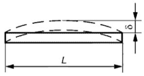 |
|
6.4 Welded connections of elements should be performed mechanized. It is allowed, in the absence of equipment for welding by mechanized methods, to use manual welding.
6.5 Materials for welding should be accepted in accordance with current regulatory documents * (5).
6.6 For bolted connections, bolts of normal accuracy must be used in accordance with GOST 7798 and GOST 1759.0, nuts in accordance with GOST 5915 and GOST 1759.5, washers in accordance with GOST 11371 and GOST 18123 and in accordance with current regulatory documents * (5)
6.7 Structures must be primed and painted. Primer and painting must comply with coating class V according to GOST 9.032.
6.8 Factory and installation joints of fencing elements should not have sharp protrusions or edges.
6.9 Completeness
The structures must be supplied by the manufacturer as a complete set.
The kit should include:
Flights of stairs, landings and fences to them;
Additional parts for connecting structures;
Bolts, nuts and washers (supplied 10% more than the specified number in the design drawings);
Technical documentation in accordance with the requirements of GOST 23118.
6.10 Marking
6.10.1 Manufactured structures must be marked.
6.10.2 A tag is attached to each package or structure, on which the following markings must be applied:
Name or trademark of the manufacturer;
Order number;
Item brand;
Number of the KMD drawing according to which the structure was made;
Date of manufacture;
Stamp of acceptance by technical control.
6.10.3 Each structural element must be marked with a symbol of the brand of the element (without the standard designation, see 5.1).
6.10.4 Markings should be applied with indelible paint on the wall of the stringer of the flight of stairs on the right side along the ascent, on the wall of the landing beam and on the upper edge of the handrail of the fence.
6.11 Packaging
6.11.1 Packing of structural elements into bags is carried out in accordance with the requirements of GOST 26663. It must prevent their mutual displacement and damage during loading, unloading, transportation and storage.
6.11.2 The weight of the package should not exceed 3 tons.
6.11.3 Connecting parts of structures and fasteners should be supplied along with structures. By agreement with the customer, it is possible to supply connecting parts separately from structures; in this case, they must be packed in wooden boxes in accordance with GOST 2991.
7 Acceptance rules
7.1 Designs to verify their compliance with the requirements of this standard must be accepted by the technical control of the manufacturer.
7.2 Monitoring of deviations of linear dimensions of structures (including cross-sectional dimensions of rolled profiles) from nominal, deviations of the shape and location of surfaces of parts from design ones, quality of welded joints and surface preparation for protective coatings should be carried out before priming of structures.
7.3 Acceptance of structures should be carried out in batches. The batch includes similar structures, manufactured using the same technology, from materials of the same quality.
The batch size is determined by agreement between the manufacturer and the consumer.
7.4 During random acceptance inspection, three structures are selected from the batch, which must be subjected to piece-by-piece inspection for compliance with the requirements established by this standard.
7.5 If, when checking the selected structures, there is at least one structure that does not meet the requirements of this standard, twice the number of structures from the same batch should be selected and re-inspected. If, upon re-inspection, there is at least one design that does not meet the requirements of this standard for one of the indicators, then this batch is rejected and sent for revision.
7.6 The consumer has the right to accept structures, applying the acceptance rules and control methods established by this standard.
8 Control methods
8.1 Monitoring deviations of the linear dimensions of structures from the nominal ones, deviations of the shape and location of surfaces from the design ones should be carried out using universal methods and means.
8.2 Quality control of welded joints and the dimensions of their sections should be carried out in accordance with the requirements of GOST 23118.
9 Transportation and storage
9.1 Structures of staircases and landings should be transported element by element or in packages consisting of several elements. Fencing structures should only be transported in packages.
9.2 Structures should be transported and stored in stacks in a horizontal position supported on wooden pads and gaskets. The pads must be at least 50 mm thick and at least 100 mm wide. Gaskets must be at least 20 mm thick and at least 100 mm wide.
The height of the stack should be no more than 1.5 m for fences and 2.0 m for flights of stairs and landings.
9.3 Conditions for transportation and storage of structures should be established depending on climatic factors of the external environment in accordance with GOST 15150.
10 Installation instructions
10.1 Installation of structures is carried out in accordance with the requirements regulatory documents for installation and the rules established by the PIC and PPR.
10.2 The installation of structures must ensure their design position, which prevents the formation of a reverse slope of steps of more than 1°.
11 Manufacturer's warranty
The manufacturer must ensure that structures comply with the requirements of this standard, subject to the conditions of transportation, storage and installation established by this standard.
_____________________________
*(1) In the Russian Federation, GOST R ISO 898-2-2013 “Mechanical properties of fasteners made of carbon and alloy steels. Part 2. Nuts of established strength classes with large and fine thread pitches” is in force.
*(2) In the Russian Federation, GOST R ISO 4014-2013 “Hex head bolts. Accuracy classes A and B” is in force.
*(3) In the Russian Federation, GOST R ISO 4759-3-2009 “Fastening products. Tolerances. Part 3. Flat round washers for bolts, screws and nuts. Accuracy classes A and C” is also in force in terms of washer tolerances.
*(4) In the Russian Federation, GOST R 21.1101-2013 “System of design documentation for construction. Basic requirements for design and working documentation” is also in force.
*(5) SP 16.13330.2011 “SNiP II-23-81 Steel structures” is in force on the territory of the Russian Federation.
Appendix A
(informative)
Layout diagrams of flight stairs

Figure A.1
In diagrams 2 - 5 of Figure A.1, the nodes marked with a circle are made rigid by welding with the help of additional elements.