The ability to read electrical diagrams is an important component, without which it is impossible to become a specialist in the field of electrical installation work. Every novice electrician must know how sockets, switches, switching devices and even an electricity meter are designated on a wiring project in accordance with GOST. Next, we will provide readers of the site with symbols in electrical circuits, both graphic and alphabetic.
Graphic
As for the graphic designation of all elements used in the diagram, we will provide this overview in the form of tables in which the products will be grouped by purpose.
In the first table you can see how electrical boxes, panels, cabinets and consoles are marked on electrical circuits:
The next thing you should know is the symbol for power sockets and switches (including walk-through ones) on single-line diagrams of apartments and private houses:

As for lighting elements, lamps and fixtures according to GOST are indicated as follows:


In more complex circuits where electric motors are used, elements such as:

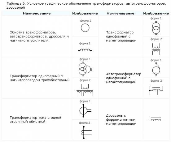
It is also useful to know how transformers and chokes are graphically indicated on circuit diagrams:

Electrical measuring instruments according to GOST have the following graphic designation on the drawings:

By the way, here is a table useful for novice electricians, which shows what the ground loop looks like on a wiring plan, as well as the power line itself:

In addition, in the diagrams you can see a wavy or straight line, “+” and “-”, which indicate the type of current, voltage and pulse shape:

In more complex automation schemes, you may encounter incomprehensible graphic symbols, such as contact connections. Remember how these devices are designated on electrical diagrams:


In addition, you should be aware of what radio elements look like on projects (diodes, resistors, transistors, etc.):

That's all the conventional graphic symbols in the electrical circuits of power circuits and lighting. As you have already seen for yourself, there are quite a lot of components and remembering how each is designated is possible only with experience. Therefore, we recommend that you save all these tables so that when reading the wiring plan for a house or apartment, you can immediately determine what kind of circuit element is located in a certain place.
Interesting video
Anyone who understands the meaning of the connections and symbols that actually make up any electrical circuit reads it like a book. The connection between the elements, their purpose and the general principle of operation of a particular mechanism immediately becomes clear. All designations on electrical circuits are a set of simple geometric shapes (circles, rectangles, squares, etc.), as well as various lines (solid, broken) and points, which are often placed at the places of their intersection (adjacency).
Any circuit often contains elements of not only “pure” electrical, but also automation, for example, the same electronics. Each type of element has its own symbols, which are reflected in the relevant standards. There are a lot of reference books in which everything is described in detail.
It is appropriate to cite GOSTs, which will be most useful when reading most electrical diagrams. The year the document came into force is indicated in brackets.
- No. 2.747 (1968) – on the sizes of symbols.
- No. 2.756 (1976) – electromechanical devices/sensing parts.
- No. 2.710 (1981) – alphanumeric designations.
- No. 21.404 (1985) – for automation elements.
- No. 2.755 (1987) – connections and switching elements.
- No. 21.614 (1988) - general symbols.
- No. 2.709 (1989) – contact connections and wires.
Among the specified standards, which reflect the symbols, there are also those that are no longer valid. But many families still use household appliances made in the USSR (for example, refrigerators), and zealous owners are in no hurry to part with them.
At least, if not in an apartment, then at least in a country house, they are definitely used, since unlike newfangled models, “old” equipment has proven its reliability in practice. If repairs are necessary, you will have to use the diagrams supplied with the units, and they are made according to outdated GOSTs.


When reading any diagram, you must pay attention to all appendices and footnotes. In particular, they must indicate the specification of elements (especially in old documentation). This information is enough to select an analogue if the required part is missing.
Any radio or electrical device consists of a certain number of different electrical and radio elements (radio components). Take, for example, a very ordinary iron: it has a temperature regulator, a light bulb, a heating element, a fuse, wires and a plug.
An iron is an electrical device assembled from a special set of radio elements that have certain electrical properties, where the operation of the iron is based on the interaction of these elements with each other.
To carry out interaction, radioelements (radio components) are connected to each other electrically, and in some cases they are placed at a short distance from each other and interaction occurs through an inductive or capacitive coupling formed between them.
The easiest way to understand the structure of the iron is to take an accurate photograph or drawing of it. And to make the presentation comprehensive, you can take several close-up photographs of the exterior from different angles, and several photographs of the internal structure.


However, as you noticed, this way of representing the structure of the iron does not give us anything at all, since the photographs show only a general picture of the details of the iron. And what radioelements it consists of, what their purpose is, what they represent, what function they perform in the operation of the iron and how they are connected to each other electrically is not clear to us.
That’s why, in order to have an idea of what radioelements such electrical devices consist of, we developed graphic symbols radio components. And in order to understand what parts the device is made of, how these parts interact with each other and what processes take place, special electrical circuits were developed.
Electrical diagram is a drawing containing, in the form of conventional images or symbols, the components (radio elements) of an electrical device and the connections (connections) between them. That is, the electrical diagram shows how the radio elements are connected to each other.

Radio elements of electrical devices can be resistors, lamps, capacitors, microcircuits, transistors, diodes, switches, buttons, starters, etc., and connections and communications between them can be made by mounting wire, cable, plug-in connection, printed circuit board tracks, etc. .d.


Electrical circuits must be understandable to everyone who has to work with them, and therefore they are carried out in standard symbols and used according to a certain system established by state standards: GOST 2.701-2008; GOST 2.710-81; GOST 2.721-74; GOST 2.728-74; GOST 2.730-73.
There are three main types of schemes: structural, fundamental electrical, electrical connection diagrams (assembly).
Structural scheme(functional) is developed in the first stages of design and is intended for general familiarization with the operating principle of the device. On the diagram, rectangles, triangles or symbols depict the main nodes or blocks of the device, which are connected to each other by lines with arrows indicating the direction and sequence of connections to each other.

Electrical circuit diagram determines what radioelements (radio components) an electrical or radio device consists of, how these radio components are electrically connected to each other, and how they interact with each other. In the diagram, the parts of the device and the order of their connection are depicted with symbols symbolizing these parts. And although the circuit diagram does not give an idea of the dimensions of the device and the placement of its parts on circuit boards, boards, panels, etc., it does allow you to understand in detail its operating principle.

Electrical connection diagram or it is also called wiring diagram, is a simplified design drawing depicting an electrical device in one or more projections, which shows the electrical connections of parts to each other. The diagram shows all the radioelements included in the device, their exact location, connection methods (wires, cables, harnesses), connection points, as well as input and output circuits (connectors, clamps, boards, connectors, etc.). Images of parts on diagrams are given in the form of rectangles, conventional graphic symbols, or in the form of simplified drawings of real parts.

The difference between a structural, circuit and wiring diagram will be shown further with specific examples, but we will place the main emphasis on circuit diagrams.
If you carefully examine the circuit diagram of any electrical device, you will notice that the symbols of some radio components are often repeated. Just as a word, phrase or sentence consists of letters assembled into words alternating in a certain order, so an electrical circuit consists of separate conventional graphic symbols of radio elements and their groups alternating in a certain order.

Conventional graphic symbols of radioelements are formed from the simplest geometric shapes: squares, rectangles, triangles, circles, as well as from solid and dashed lines and dots. Their combination according to the system provided by the ESKD standard (unified system of design documentation) makes it possible to easily depict radio components, instruments, electrical machines, electrical communication lines, types of connections, type of current, methods of measuring parameters, etc.
As a graphic designation of radioelements, their extremely simplified image is taken, in which either their most general and characteristic features are preserved, or their basic principle of operation is emphasized.
For example. A conventional resistor is a ceramic tube, on the surface of which is applied conductive layer, having a certain electrical resistance. Therefore, on electrical diagrams, a resistor is designated as rectangle, symbolizing the shape of a tube.

Thanks to this construction principle, memorizing conventional graphic symbols is not particularly difficult, and the compiled diagram is easy to read. And in order to learn how to read electrical circuits, first of all, you need to study the symbols, so to speak, the “alphabet” of electrical circuits.
We'll leave it at that. We will analyze three main types of electrical circuits that you will often encounter when developing or reproducing electronic or electrical equipment.
Good luck!
When, while going fishing, suddenly in the evening the headlights on a personal car do not light up, some drivers clutch their heads. They don't know how to read car wiring diagrams and A breakdown of this kind immediately becomes an insoluble problem.. For this reason, learning to read electrical circuits is not just a whim, but a necessity for the normal use of an iron horse.
Types of electrical circuits
Learning everything unknown usually begins with the basics or initial concepts. To learn how to read electrical circuit diagrams, learn what they are and why they are needed. Here are the main types:

The type of such images is determined by its purpose. For example, assembly requires one plan, the concept of the operating principle requires another, repair requires a third, and so on.
Legend
When faced with an electrical circuit for the first time, a beginner may think that this is a Chinese letter. However, having mastered the basic notations and principles of construction, very soon reading electrical diagrams for beginners can become commonplace. To begin with, we define the main parts of any documentation of this kind. These are three groups of constituent elements with common functions:

Symbols have been invented for all components of the electrical circuit. The icons are arranged in the order in which they are connected by electrical wiring, and not by their literal location. That is, two light bulbs can be located side by side on the device, but in the diagram - in parts opposite from each other. Elements connected to the same voltage in a circuit are called a branch. They are connected by nodes. Nodes in the diagram are highlighted with dots. Closed paths can contain multiple branches. The simplest electrical circuits - these are images of single circuit circuits. The most complex ones are multi-circuit ones.
To study the decoding of symbols, use special reference books. In addition to symbols, the diagrams use explanatory inscriptions and indications of markings of the electrical equipment and parts used.
Reading order
Essentially, an electrical circuit is a drawing. It shows the design of electrical equipment using symbols. Knowing the basic principles of constructing such drawings and symbols, you can master reading electrical circuits. For beginners, this is exactly what you need. Thus, it is easiest to train on simplified drawings than on those where all the details are shown.
To read diagrams correctly, learn a simple algorithm of actions that will help you not miss important details. Here is the sequence of studying the electrical circuit:

It is very difficult for a novice electrician to understand such circuits. However, once they know the basics, they can make simple electrical repairs using their car's wiring diagram.
Today I want to once again touch on such an interesting topic as reading electrical diagrams.
I already talked about it in one of the videos on my YouTube channel “how to read electrical diagrams” Using a lathe as an example (see this video at the end of the article), then I answered the question of one of the readers who had difficulty understanding the electrical circuit.
This topic turned out to be very interesting for many and now I want to tell you how to “read” an electrical circuit diagram relay protection in the energy sector.
Or rather, it will not be me who will tell the story, but Dmitry Vasilevsky, who is professionally engaged in the design of relay protection and automation. By the way, here is Dmitry’s video channel on YouTube, go and subscribe to the news, I personally really like how Dmitry clearly and clearly conveys complex information on relay protection.
Dmitry Vasilevsky. How to work with a relay protection circuit diagram?
Schematic diagrams of relay protection and automation kits are the second most important and complex in the entire project. Regardless of what you need to do - develop a concept or check a finished one, working with it requires certain qualifications. Looking, for example, at the relay protection circuit diagram of a 110/10 kV transformer, at first you don’t know what to grab onto. Yes, there is a 110 kV transformer, sometimes a 10 kV input is enough to make it “dark in the eyes” 
How to simplify working with a circuit diagram without sacrificing quality?
Next I will talk about the techniques that I use myself.
We eat the elephant in parts
If you look at the whole diagram at once, then nothing good will most likely come out - there is too much information. You must divide the circuit into independent sections and work with each separately. For relay protection circuits with microprocessor terminals, such sections can be divided into 10:
1. Explanatory diagram;
2. Measuring circuits (current and voltage circuits);
3. Switch drive circuits;
4. Operating current circuits (including terminal power supply);
5. Alarm circuits;
6. Output circuits (including vehicle circuits and backup outputs);
7. ACS circuits;
8. Auxiliary circuits (heating, lighting, sockets, etc.);
9. List of elements (can be separate from the principle);
10. Tables or logical diagrams for parameterization (can be separated into a separate part).
Advantages:
1) You can check the completeness of the data on the diagram.
Not every relay protection kit contains all 10 sections, but if a section is missing, then ask yourself why it is not there? If you can adequately answer this question, then everything is in order, but if you find it difficult, then there is a high probability of error.
Example:
Question: why are there no drive circuits included in the 10 kV transformer kit (item 3)?
Answer: because there is no switch in the TN cell. This is quite logical.
Another example:
Question: why is the 10 kV input relay protection kit missing information for parameterizing the relay protection terminal (clause 10)?
Answer:... no answer. This means this is an error, especially if the terminal has flexible logic.
And so on. Since the brain works much faster than you read these examples, it's actually not that boring
2) You get a clear circuit verification system
Instead of intuitive feelings, you actually have a checklist in which you need to go through all the points and tick all the boxes.
You can save this Checklist and pass it on to other people. For example, to the contractor before developing circuits in order to reduce the number of errors.
Systemic knowledge is much more valuable than intuitive knowledge.
“Not all chains are created equal”
The previous section shows 10 sections of the circuit diagram. For now this is just a list of tasks. We need to prioritize their implementation!
 You must understand - there are many circuits, but there are several critical ones that determine 80% of the circuit's performance. There are not many of them - about 20% of the total. If this relationship seems familiar to you, it doesn't.
This is the Pareto Principle - 20% of efforts give 80% of results.
His influence can be seen everywhere - not just in relay protection. The percentages themselves are not important and can vary widely. For example, not 20/80, but 10/90. The important thing is that we cannot devote equal effort and time to all parts of the circuit. The result will be bad.
Especially if you are short on time! And when designing, this usually always happens
What are the most critical areas of the circuit diagram?
I believe that the following (for relay protection and automation of a specific connection):
– Measuring circuits (100% critical);
– Circuit breaker drive circuits (100% critical);
– Operating current circuits (approximately 40% of these circuits are critical - the rest are auxiliary)
– Output circuits (approximately 40% of these circuits are critical - the rest are auxiliary);
– Tables or logical diagrams for parameterization (for MP relay protection and automation, approximately 30% of the functions are critical - the rest are auxiliary).
If you don’t know what to take on, take on these chains and make them well. This will allow you to avoid serious errors in the design and, in the future, major accidents at the site.
This is advice primarily for novice designers. I was like that myself and messed up terribly because I grabbed at everything and usually not what I needed
Advantages:
Effective work under time pressure and large amounts of information
P.S. This principle does not mean that the remaining circuits do not need to be made. It is necessary, of course, but last of all, after all the critical work has been completed.
Find errors before you see the diagram
My former boss once said that “professionalism is the ability to anticipate mistakes.” Although I was not involved in relay protection then, I remembered his words and apply this principle in my current work.
The point is that in each section of the diagram there are mistakes that are made most often. If you know these “typical errors,” then working with the circuit becomes quick and easy.
For example, for the current circuits of a relay protection and automation kit, the most common error is a violation of polarity when connecting the CT to the terminal. This mistake is so frequent and widespread that I even decided to make a video about creating current circuits. If you are interested, you can find the first video here http://www.youtube.com/watch?v=9Cqyxg1bSy4
Other videos on the same channel.
For drive circuits, this is the spring charging contact (ready to turn on). Somewhere it is closed, somewhere it is open. Here it is worth looking at the diagram together with the terminal algorithms.
For operational current circuits, these are usually control keys and control mode selection keys (MU/RC). The topic seems simple, but there are a lot of options for execution. Moreover, different operating organizations sometimes have completely opposite opinions. Also a “fun” topic is arc protection circuits, especially at generation facilities. I'm one of the first to watch them.
It is especially effective to use this technique with the second one, i.e. look for “typical errors” in critical circuits!
This is also very useful when assessing the level of a project or designer - you quickly look for blunders. If they are there, you don’t have to watch the rest. Everything is already clear.
The third method is probably the most difficult of all because it requires a certain level of knowledge and experience. Unfortunately, they don’t teach this at the institute. The first two can be started to be used immediately, without additional preparation.
Example of reading a lathe diagram:
Dmitry Vasilevsky: How to work with the circuit diagram of relay protection and automation.
I will be glad to see your comments, if you have any technical questions, please ask them on the forum, that’s where I answer questions - .
Subscribe to my channel on YouTube !
Latest video from the “Electrician Tips” channel:
Watch many more home electrical videos!
Be the first to know about site news!