Most manufacturers of underfloor heating produce only one type of heating system - electric or water. This somewhat limits the buyer's choice. But Rehau heated floors do not have this drawback. German company offers electric and water heating systems.
About the Rehau brand
The Rehau company took its first steps back in 1948. Initially, the staff consisted of only 3 people. In the 60s it was established PVC production– profiles, as well as pipes made of cross-linked polyethylene, which became a turning point in the development of the company.Today Rehau occupies a leading position in the production of energy-efficient systems for the construction of industrial and private facilities. The domestic consumer mainly knows about the company thanks to the products offered by Rehau metal-plastic windows and warm electric and water floors.

Warm water floors Rehau
The company offers a heating system that is completely ready for installation. The basic package includes:

The functionality of the mixing unit and manifold is guaranteed only if the system is installed using components from the same manufacturer.
Warm electric floors Rehau
Rehau electric underfloor heating is another unique development of the company. The buyer is offered a two-core heating wire and mats.Regardless of the choice of heating system, Rehau electric underfloor heating has the following distinctive characteristics: 

If, before laying the cable, you preheat the wire by connecting it to the power supply system, you can achieve greater elasticity of the braid and make installation easier.
Pros and cons of Rehau underfloor heating systems
The main advantage of water and electrical systems heating systems created by Rehau are as follows:- Technical characteristics of Rehau heated floors– system parameters: power, heat dissipation, performance are significantly superior to analogues from other manufacturers. Specially designed fasteners for Rehau pipes facilitate installation and speed up the installation process.
- Complete system– the consumer is offered installation kits for Rehau equipment, fittings and all other consumables.
- Quick installation - all system components, control and shut-off valves fit perfectly together. The use of additives and additives manufactured at the plant speeds up the hardening process of the screed and increases its strength. Plasticizer consumption is from 0.6 l to 1 l per m².
- The Rehau pipe calculation method allows you to prevent excess material consumption and, accordingly, avoid unnecessary material costs.
- Durability and durability– cross-linked polyethylene pipes are guaranteed to last at least 40 years.
Water-based types of heated floors continue to improve, remaining popular among consumers. One of the recognized leaders is the Italian company Valtec.
Pros of the Valtec system
Before starting installation and selecting a mixing unit for a Valtec heated floor, it is necessary to analyze the advantages of this type of water circuit.
- Thanks to quality materials, durable fasteners ensure reliable operation.
- Developed in the form of modules, the components fit together precisely, eliminating the risk of leaks.
- The manufacturer has provided for the release related materials necessary for thermal and waterproofing equipment.
Calculation instructions
In order to correctly develop a project for laying a heated floor, you will need a preliminary calculation of the main indicators, focusing on their average values.
Do-it-yourself installation of water heated floors
Various factors have to be taken into account, including the role of the water floor as the main type of heating or its use as an additional heat source. Since detailed calculation for self-execution is a complex process; in practice, average parameters are used.

Once the key parameters have been determined, a diagram can be developed in which exact scale The most rational pipe laying is determined. After this, their total length is calculated. At the same time, it is thought through where the pumping and mixing unit and control elements will be located.
Key characteristics of the mixing unit
In order for the installed water circuit to function effectively, it is necessary to correctly calculate the entire system and correctly install the mixing unit for the Valtec heated floor in accordance with the provisions reflected in the instructions included with the kit.

Parameters of the pumping and mixing unit:

The pipes have an external thread with a Eurocone connection.
Pumping and mixing unit for heated floors
Functionality
The main purpose of the pumping and mixing unit is to stabilize the temperature of the coolant when entering the water circuit by using water from the return line for mixing. This ensures optimal functioning of the heated floor without overheating.
The Combi unit design includes the following service elements:

The following organs are used to adjust the unit:
- a balancing valve on the secondary circuit, which ensures mixing in the required proportion of coolants from the supply and return pipelines to ensure the standard temperature;
- balancing shut-off valve on the primary circuit, responsible for supply to the unit required quantity hot water. It allows you to completely shut off the flow if necessary;
- a bypass valve that allows you to open an additional bypass to ensure the pump operates in a situation where all control valves are closed.
The connection diagram has been developed taking into account the possibility of connecting to the pumping and mixing unit the required number of floor heating branches with a total water consumption not exceeding 1.7 m 3 /h. The calculation shows that a similar amount of coolant flow with a temperature difference of 5°C corresponds to a power of 10 kW.
In the case of connecting several branches to the mixing unit, it is advisable to select collector blocks from the Valtec line with the designation VTc.594, as well as VTc.596.
Installation algorithm
After the preliminary calculation of all components has been completed, the actual installation of the heated floor begins, which involves going through several stages.

Settings
A pipe cutter is used to connect pipes to distribution manifolds. required length, calibrator, chamfering and compression fitting. It is difficult to carry out detailed calculations at home, so be sure to study the instructions, which detail the settings of the pumping and mixing unit in a certain sequence.

k νb = k νt ([(t 1 – t 12) / (t 11 – t 12)] – 1),
where k νt – coefficient = 0.9 bandwidth valve;
t 1 – supply water temperature of the primary circuit, °C;
t 11 – temperature of the secondary circuit at the coolant supply, °C;
t 12 – return pipeline water temperature, °C.
The calculated value k νb must be set on the valve.

Consumption G 2 (kg/s) is determined by the formula:
G 2 = Q / ,
where Q – total thermal power water circuit connected to the mixing unit, J/s;
4187 [J/(kg °C)] – heat capacity of water.
To calculate pressure loss it is used special program hydraulic calculation. To determine the pump speed, which is set using a switch, according to the calculated indicators, a nomogram is used, which is in the instructions attached to the heated floor design.

- Operations are being performed to adjust the balancing valve on the primary circuit.
- The thermostat sets the temperature required for comfortable heating.
- A trial run of the system is being carried out.
If there are no leaks, all that remains is to make a concrete screed, and after it has completely hardened, lay the flooring.
Video: Warm floor with pumping and mixing unit VALTEC
Description temperature control kit Rehau with constant parameters G1 (1")
Rehau temperature control kit with constant parameters G1 (1") ErP is suitable for installation on the Rehau NKV-D manifold. Designed for connecting underfloor heating circuits to a radiator heating system.
Includes:
thermostatic valve Rp 1/2 with thermostatic head and immersion sensor: adjustment range 20-50 °C
return connection r R/Rp 1/2
energy efficient pump with immersion sensor for temperature limitation
connecting elbow with air vent and thermometer
KFE 1/2" tap for filling and draining the system
included 1/2" parts for mains connection
The individual parts are mounted with seals and tested.
In the Torus online market you can buyRehau temperature control kit with constant parameters 1"with delivery to any point in Ukraine and receive official guarantee from the manufacturer.
Delivery in Kyiv
Delivery of goods in Kyiv is free of charge (to the front door) for orders over UAH 4,000. If the order amount is less than 4000 UAH, the delivery cost is 80 UAH.
The delivery service for goods in Kyiv operates from Monday to Friday from 10:00 to 19:00, other delivery times are negotiated individually with your manager.
Buyers of our online market also have the opportunity to pick up the goods themselves at the company’s office (04073, Kiev, Syretskaya St., 9, BC "MAYAK", office 203) from Monday to Friday from 10:00 to 18:00.
Please note that, unfortunately, we cannot place the entire range of goods in the office; please coordinate your visit and reserve the goods with the manager in advance.
Delivery throughout Ukraine
Delivery of goods is carried out almost anywhere in Ukraine transport company"New Post" (List and addresses of branches you can see here...). The goods are dispatched after payment of its full cost.
For speedy delivery and ease of payment in our Torus online market, you can use the "Return delivery" (Cash on delivery) service and pay for the goods upon receipt in your locality in the shortest possible time. Upon receipt of your order, you can check appearance and product packaging.
The cost of delivery within Ukraine is paid by the recipient. (You can calculate the preliminary delivery cost →)
Cash
Produced only in national currency. You can make payment directly after our forwarder delivers the ordered goods, or you can make payment when placing an order in our office.
Cashless payments
Payment by bank transfer is carried out in the following way: after placing an order, our company manager by fax or by email will send you an invoice, which you can pay at the cash desk of any bank branch or from the current account of your organization. For legal entities package of all necessary documents provided with the product.
Payment for goods upon receipt of the order(C.O.D)
For your convenience, in the Torus online market, you can use the “Return Delivery” (Cash on Delivery) service and pay for the goods upon receipt in your locality as quickly as possible. Upon receipt of your order, you will be able to check the appearance and contents of the product.
The cost of the "Return delivery" service is 2% of the order amount.
Underfloor heating systems, which few people had heard of a decade and a half ago, have firmly become part of the everyday life of modern houses and apartments, especially among those owners who are thinking about creating maximum comfort residence in their possessions. There are a lot of advertisements in advertising newspapers about services for installing floor heating systems, but such is the “design” of many of our men that they are simply “itching” to do everything on our own.
Thus, in conventional high-temperature systems, water heating in supply pipes usually balances at the level of 70÷80 °C, and in some cases it can even exceed these limits. It is for these operating modes that heat mains were created earlier and are now predominantly created, and the vast majority of models of boiler equipment are produced.
But those temperature conditions, which are considered the norm for classical heating systems, are completely unacceptable in the operating conditions of “warm floors”. This is explained by the following circumstances:
- If we take into account the area of active heat exchange (almost the entire surface of the floor in the room), and add here the very impressive heat capacity of the screed in which the “warm floor” pipes are enclosed, then it is obvious that in order to achieve a camphor temperature in the room, much heating is not required .
- The threshold for comfortable perception of heating the floor surface with bare feet is also limited - usually a temperature of up to 30 ° C is sufficient for this. Agree, it won’t be particularly pleasant if it starts to “cook” from below.

- The vast majority of finishers floor coverings, used in living rooms, is not designed for strong heating. Exceeding the temperature above the optimum leads to deformations and the appearance of gaps between individual parts, to failure lock connections, to the formation of waves or “humps” and other negative consequences.

- High heating temperatures are quite capable of destructively affecting the condition concrete screed, in which the pipes of the “warm floor” circuits “rest”.
- Finally, elevated temperatures are not at all beneficial for the pipes of the installed circuits. It should be correctly understood that they are rigidly fixed in the screed, deprived of the possibility of free thermal expansion, and when high temperatures Very strong internal stresses will arise in the pipe walls. And this is a direct path to rapid wear and increased likelihood of leaks.
Recently, models have appeared on sale that can operate in “warm floor” mode, that is, provide low-temperature heating. But is there any point in purchasing new equipment if you can get by with the existing ones? In addition, “warm floors” in their “pure” form are not used so often - usually they are combined with “classics” on the scale of one house. Install two separate boilers? - very wasteful. It is better to improve your system somewhat by separating out a section of “warm floors” from it, and at the border of this division, install the very pumping and mixing unit that will be discussed.
There is one more circumstance that explains the need for a pumping and mixing unit. It’s one thing to ensure circulation in the main heating circuit, and another thing to ensure circulation in the heated floor circuits, each of which reaches a length of tens of meters, with numerous bends and turns that give a significant increase in hydraulic resistance. This means that dedicated pumping equipment is needed, which is also, as a rule, included in the design of this unit, which, by the way, is reflected in its name.
Operating principle of the mixing unit
The task is clear - it is necessary, without disturbing the operating mode of the main heating system, to ensure that the coolant circulates in the “warm floor” circuits with much more low level heating How to achieve this?
The answer suggests itself - qualitative regulation, that is, mixing a colder one into a hot stream. A complete analogy with what we do repeatedly every day, adjusting the temperature of the water in the shower or in the kitchen faucet.
Prices for heated floors
warm floor

With a hot stream - everything is clear, but where to get a cooled one? Yes, from the “return” pipe passing nearby, through which the coolant, which has given off heat in heating devices or in the “warm floor” circuit, returns back to the boiler room. By changing the proportions of mixing hot and cooled liquid, you can achieve the required temperature.
Of course, in terms of the complexity of the device, the mixing unit differs very significantly from a conventional household tap. So the tasks before him are more responsible!
Thus, the mixing unit must be able to operate without constant human intervention - automatically monitor temperature levels and make operational changes in the process of mixing flows, changing them quantitatively. Often a situation arises when additional income There is no need for heat at all, and the equipment should simply “lock” the circuit, providing only internal circulation of the coolant through it, until the required cooling.
One gets the impression that all this is very complicated for a non-specialist. Indeed, if you look at the factory-made pumping and mixing units offered for sale, then, at first glance, you will understand the intricacy of pipes, taps, valves, etc. – very difficult. And the cost of such assemblies looks very scary.

But it turns out that in practice only a few common schemes are implemented, and if you understand the principle of their operation, it is quite possible to assemble such a pumping and mixing unit on your own. We will devote the next section of our publication to the analysis of these schemes.
It is necessary to make one thing clear right away - this article is dedicated specifically to pumping and mixing units, but the supply and return manifolds connected to them will certainly be mentioned, but we will not delve into their design. Simply for the reason that this unit of the “warm floor” system, namely its structure, principle of operation, assembly and balancing procedure, still requires detailed consideration in a separate publication.
Schemes of pumping and mixing units and principles of their operation
Of the variety of designs for such mixing units, five were selected. The main selection criteria were ease of understanding of the operating principle and accessibility to self-production. That is, the proposed structures can be assembled from parts that are commercially available, and this does not require special training - sufficiently stable skills in carrying out ordinary plumbing installation.
The diagrams, of course, differ, but to make them easier to understand, they are made according to the same graphic principle, preserving the images and numbering of the same elements. New parts that will appear in the diagrams will be assigned letter designations ascending.
In all schemes, one orientation is adopted - the supply and return pipes are supplied on the left, and the outlet to the "combs" - the heated floor collector - is on the right. The color marking of pipes clearly indicates their purpose. In reality, the collector itself can be directly adjacent to the pumping and mixing unit (this happens more often) or even located at some distance from it - this depends on the characteristics of the room and the free space for placing the equipment. This does not affect the principle of operation of the circuit at all.
Any pipes can be used, at the request of the master - from ordinary steel VGP to plastic (polypropylene or metal-plastic) or corrugated stainless steel. Some components will also change accordingly. For example, the diagrams show brass tees or bends, but they can also be made of other materials.
The corresponding thickened arrows with variable shades show the directions of coolant flows.
SCHEME No. 1
This circuit uses a conventional thermal valve, as for heating radiators. The circulation pump is located in series.
The circuit is considered one of the simplest to install, but it is quite effective.

Let's take a closer look at the details and devices that make up the circuit:
- "A"– pipes shown color coded for ease of reference. As already noted, they can be used Various types pipes, as long as they correspond in their characteristics to the operating conditions in the heating system.
- "a.1"– inlet of the supply pipe from the general circuit of the heating system;
- "a.2"– exit to the “return” pipe;
- "a.3"– supply to the “warm floor” collector;
- "a.4"– return of coolant from the collector.
- "b"- shut-off valves – Ball Valves. Important - they do not play any role in the process of adjusting the temperature or pressure in the “warm floor” system. Their functionality is limited, but at the same time – no less important. The presence of taps allows you to turn off individual components of the heating system when this is caused by the need, for example, to carry out any repair and maintenance work.

There are no special requirements for the design of shut-off valves for the mixing unit, except, perhaps, for the quality of their execution. But it is advisable to use taps equipped with an American union nut (as shown in the illustration), which will allow you to quickly dismantle the unit without resorting to complex operations. Accordingly, at the entrance (“b.1” And "b.2") these union nuts must be on the mixing unit side.
Cranes "b.3" And "b.4"(between the mixing unit and the collector) cannot be called mandatory elements of the system, but it is better not to spare money on them. Their presence allows you to turn off the collector and completely dismantle the unit without disrupting the adjusted balancing of the circuits.
- "V"— a filter for mechanical purification of the coolant (it is often called an “oblique filter”).

This element may not be installed, but only if there is complete confidence in the purity of the circulating coolant. Typically, filter devices are provided at the boiler room level. However, in order to completely eliminate the possibility of solid suspensions getting into the area of precise adjustment of “warm floors”, you can play it safe.
Such a filter is inexpensive, but it will guarantee that no solid particles that can disrupt their correct operation will get into the valve devices of the mixing unit itself and the adjusting mechanisms of the circuits. In addition, it should be remembered that solid suspensions in the coolant accelerate the wear of valve seals.
- "G"– devices for visual monitoring of coolant temperature (thermometers).

The thermometer can be of any type - as convenient for the master. Thus, devices with probes are used that are in direct contact with the coolant. To put it simply, you can purchase an overhead model, but the measurement will be based on the temperature of the pipe wall. The thermometer can be liquid, mechanical with a dial indicator, or even digital - it is convenient to use electronic systems control of heating systems.
The diagram shows an option using three thermometers:
— "g.1"– measures the temperature in the common supply pipe of the heating system;
— "g.2"– to control the temperature of the coolant supplied from the mixing unit to the collector;
— "g.3"– allows you to monitor the temperature difference at the inlet and outlet of the collector. Optimally, this difference should not exceed 7÷10 degrees.
This arrangement of devices seems optimal, as it gives the most complete picture of the correct operation of the system. However, many craftsmen, for reasons of economy, make do with fewer thermometers.
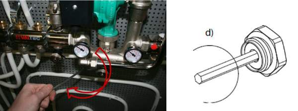
- "d"– the main control element of the mixing unit of this design is the thermostatic valve. This is exactly the same valve that is usually mounted on radiators.

A little subtlety. On sale are valves for radiators designed for single-pipe and two-pipe system heating. In our case, for the mixing unit, the model for single pipe system as more productive. It is easy to distinguish by a number of characteristics: such a valve has several larger diameter“barrel”, the marking contains the letter « G", and the protective cap is gray.
The direction of coolant flow is indicated on the valve body by an arrow.
- "e"– a thermostatic head, which is placed on the thermal valve (using an M30 union nut or a special type of fixation). Important - in this case, only a head with an external sensor is required ( "and"), connected to it by a capillary tube.

The design of the head is such that when the temperature changes, its mechanical effect on the thermal valve rod also changes - when it increases, the valve closes, when it decreases, on the contrary, it opens the passage for the coolant.
How do thermostats for heating radiators work and how do they work?
In this publication we will not dwell on these devices in detail. This is from considerations that are discussed in detail in a separate article on our portal.
The temperature sensor is placed on the pipe - there are special spring clamps for this. But the question immediately arises: where exactly should it stand?
There are two options, each of which is good in its own way.
— First option: the sensor is located on the supply pipe from the mixing unit to the “warm floor” manifold. The advantages of this approach are that coolant with a stable temperature enters the circuits, that is, the possibility of overheating is completely eliminated. Disadvantages - the mixing system does not react in any way to changes in external temperature (unless, of course, the corresponding additional devices are placed on the collector itself). For example, when the room gets cold or the temperature rises, the mixing unit will still supply coolant to the circuits with a constant heating level.
— Second option: the sensor is located on the return pipe from the manifold to the mixing unit (up to the jumper, in the area of the thermometer “g.3”). The advantages are temperature stability in this particular area, that is, taking into account the heat already released into the room. But the heating level of the coolant in the supply pipe to the collector will vary in accordance with the change external conditions. It got colder in the room - the circuits gave off more heat - the thermal valve opened slightly more, and accordingly, vice versa. Disadvantages - the possibility of overheating in the “warm floor” circuits. For example, after filling the system during its first start-up, too much water will be supplied to the collector at first. hot water until the screed warms up. Another option is that the temperature in the room becomes too cold (for example, emergency ventilation by opening the windows wide) can also give an influx of coolant into the circuits that is too hot for them.
However, with thoughtful operation, all this negativity can be avoided. Better yet, provide areas for placement on both pipes in the locations indicated above. Rearranging such a sensor is a minute task that does not require any tools.
- "z"– plumbing tees, with the help of which a jumper is formed between the supply and return pipes - bypass ( "And"). Through this bypass, the cooled coolant will be taken out for mixing. And the mixing process itself, in fact, takes place in a tee "z.1".
- "To"– balancing device. It is recommended to install a valve on the bypass (you can even use a regular plumbing valve), which can be used to fine-tune the system after it has started, in particular, the required pressure and performance of the circulation pump. The presence of such an adjustment allows you to “strangle” the flow so that zones with excessively high pressure or, conversely, vacuum do not form in the collector and the mixing unit itself. The pump will operate in the most optimal mode, and the noise of the system will decrease.

The optimal solution is to install not a plumbing valve, but a so-called block tap, such as is often installed on the “return” of a heating radiator. In terms of functionality, in principle, there is no difference, but in terms of ensuring the safety of settings, it is obvious. Balancing is carried out with a special key, and after that the adjusting device is closed with a protective plug. That is, playful children’s hands, for example, cannot reach it.
- "l"– a circulation pump that ensures the movement of coolant along the “warm floor” circuits.

The main heating system, of course, has its own pumping equipment, but “ heated floors» as a rule, a separate pump is allocated, taking into account the length and branching of the laid pipe circuits. The pump is a regular one, and its parameters are calculated individually for each mixing unit - this will be discussed below.
Prices for thermal valves
thermal valve
Circulation pumps - device, principle of operation, selection of the optimal model
Heating systems with natural circulation are becoming less and less common - preference is given to schemes with an installed pumping equipment. How it works and what evaluation criteria are used to select it - read in a special publication on our portal.
- "m"– plumbing check valve. This is a familiar part that allows fluid flow only in a given direction.

How necessary is it? In the mixing process, of course, it does not play any role, but to ensure constant correct operation it can be useful. Let's imagine a situation - the temperature in the circuits is such that no heat flow is required, and the thermal valve is completely closed. But the pump continues to work, and circulation in the circuits does not stop. And here the phenomenon of coolant suction from the common return pipe of the heating system is possible. But the temperature there is even much higher than it should be in the “warm floor” supply. Such an influx of unauthorized heat can greatly unbalance the operation of the mixing unit, but installing a valve completely removes even the slightest likelihood of such a phenomenon.
Now let's move on to consider the principle of operation of this scheme.
The coolant comes from a common supply pipe and is further purified using an “oblique filter”. The flow at the thermal valve is noticeably reduced due to the covered valve, which reduces the free passage cross-section. The thermostatic head is responsible for changing the position of the valve, transmitting mechanical force to its stem, depending on the temperature at the remote
The circulation pump operates constantly, and in front of it, in the area of the tee “z.1”, a vacuum zone is created, which draws in both the changing flow of hot coolant and cooled coolant from the return pipe through the bypass. The flows are connected precisely in the mentioned tee, mixed, and in this form, with the required temperature, are pumped further to the “warm floor” manifold.
If the temperature sensor shows that the heating level is sufficient or even excessive, the valve will be completely closed and the pump will simply pump the coolant in a circle, without its influx from the outside. As the coolant gradually cools, the valve will open slightly to add another “portion” of heat, so that the temperature takes on the required value.
As you can see, the influx of hot coolant in a well-functioning system will not be particularly large - in the normal position, with stable operation of the unit, the valve is barely open. But if external conditions change, the thermal head will make the necessary adjustments.
In this scheme, the circulation pump is located in such a way that it completely pumps the entire coolant flow to the “warm floor” collector. This principle is called series pump arrangement.
SCHEME No. 2
The circuit largely repeats the first one, but instead of a conventional thermal valve, it uses a three-way valve.

So, let's look at the design features:
Instead of the upper tee, a three-way thermal mixing valve is installed ( "n"), and the usual valve is, accordingly, removed from the circuit. This device is controlled by the same thermal head with a remote sensor as in the first scheme. The position of the sensor also does not change - one of the two options mentioned above.

Mixing of flows occurs directly in the body of the three-way valve. It is designed in such a way that when the position of the rod changes, one passage opens slightly and the second closes proportionally.
It is necessary to pay special attention to one nuance. Such valves can have not only a mixing principle, but also, conversely, a separation principle of operation. In the diagram shown, a mixing valve is required, that is, with two converging flows. As a rule, there is a corresponding indication on the product body - arrows showing the direction of coolant flows.

The shown diagram may have another variation - a thermal valve is installed instead of the lower tee, but here, of course, there should already be a separating type of product. That is, the temperature will be controlled by changing the supply flow from the return.

Three-way valves may not require a thermal head - many models have their own built-in temperature sensors. True, some experts express the opinion that with a remote sensor the system still works more correctly, and the likelihood of emergency situations occurring is much lower.

The diagram also shows (translucent) (“m1”) installed on the bypass. It is necessary in cases where the automation also controls the operation of the circulation pump. If there is no valve, then in idle circulation mode the bypass becomes an ordinary uncontrolled jumper, which immediately affects the balance of the unit and the operation of other heating devices in the heating system. But in most cases, when the pump operates constantly, such a part is not required in the circuit, and many craftsmen generally consider it harmful, since such a valve creates additional hydraulic resistance.
When is it beneficial to use such a three-way valve circuit? As a rule, it finds application in large mixing units, to which several circuits are connected, and of varying length. One is also justified in heating systems that are controlled by weather-dependent automation, since the change in parameters in them occurs not only due to the valve, but also due to changes in the operating modes of the circulation pump. In small systems, the use of such a scheme is not particularly welcome, since it will be more difficult to adjust.
SCHEME No. 3
Another variation of the circuit with a sequential arrangement of the circulation pump. This time a three-way thermal valve is also used ( "n.1"), but with a different layout - it mixes two flows converging along one line and redirects them to the central pipe.

Such valves have appropriate markings - arrow or color, which allows you to avoid making a mistake in your choice.

The rest of the scheme is a complete analogue of the previous one. There may be no bypass at all - a three-way valve is installed instead, which saves considerable space and makes the circuit more compact.
SCHEME No. 4
This and the following diagram are fundamentally different from those discussed above, and this fundamental difference lies in the location of the circulation pump

As can be seen from the diagram, no new elements appeared in it. The supply and return pipes on the side of the general system remained in place, but on the side of the collector they swapped places. The bypass, of course, remains, but it turns out that the flows of hot and cooled coolant meet at its highest point. And on the bypass itself there is a circulation pump that provides pumping from top to bottom.
The principle of operation is as follows. The flow of hot coolant passes through the thermal valve, where it is dosed to the required amount, and meets in the upper bypass tee with the flow from the “return” of the collector. The pump standing on the bypass captures both of these flows and pumps them down. Thus, mixing occurs both in the upper tee and in the working chamber of the pump itself.
At the lower point of the bypass, at the tee, the flow is again divided. Most of the pumped coolant has already desired temperature usually returns to the collector and then to the “warm floor” circuits. And the resulting excess is simply discharged into the “return” of the main circuit of the general heating system.
— The performance of the system decreases, since part of the mixed coolant is simply discharged into the return line.
— Such a scheme is much more difficult to balance, since it is necessary to achieve complete constant filling of the “warm floor” circuits, without areas of rarefaction, and only the excess amount is sent to the “return”. This often requires the installation of additional balancing elements, such as block valves or bypass valves.
The VALTEC COMBIMIX (VT.COMBI) pump and mixing unit is designed to maintain a given temperature of the coolant in the secondary circuit (due to mixing from the return line). Using this unit, it is also possible to hydraulically link an existing high-temperature heating system and a low-temperature underfloor heating circuit. In addition to the main regulatory bodies, the unit also includes all necessary set service elements: air vent and drain valve, which simplify maintenance of the system as a whole. Thermometers make it easy to monitor the operation of the unit without the use of additional devices and tools.

It is permissible to connect an unlimited number of heated floor branches with a total power of no more than 20 kW to the VALTEC COMBIMIX node. When connecting several branches of a heated floor to a node, it is recommended to use VALTEC VTc.594 or VTc.596 collector blocks.
The main adjustment elements of the pumping and mixing unit:
1. Secondary circuit balancing valve (position 2 on the diagram).
This valve ensures mixing of the coolant from the return collector of the heated floor with the coolant from the supply pipeline in the proportion necessary to maintain the specified temperature of the coolant at the outlet of the COMBIMIX unit.

The valve setting is changed using a hex wrench; to prevent accidental rotation during operation, the valve is secured with a clamping screw. The valve has a scale with capacity values Kv τ valve from 0 to 5 m 3 / h.
Note: Although the valve capacity is measured in m3/h, it is not the actual coolant flow rate passing through this valve.
2. Balancing shut-off valve of the primary circuit (pos. 8 )
Using this valve, the required amount of coolant is adjusted that will flow from the primary circuit to the unit (unit balancing). In addition, the valve can be used as a shut-off valve to completely shut off the flow. The valve has an adjusting screw with which you can set the valve capacity. The valve is opened and closed using a hex key. The valve has a protective hex cap.

3. Bypass valve (pos. 7 )
During operation of the heating system, a mode may arise when all control valves of the heated floor are closed. In this case, the pump will operate in a muted system (without coolant flow) and will quickly fail. In order to avoid such modes, there is a bypass valve on the unit, which, when the valves of the underfloor heating system are completely closed, opens an additional bypass and allows the pump to circulate water through a small circuit in idle mode without loss of functionality.

The valve is activated by the pressure difference created by the pump. The pressure difference at which the valve opens is set by turning the regulator. On the side of the valve there is a scale with a value range of 0.2-0.6 bar. Pumps recommended for use with COMBIMIX have a maximum pressure of 0.22 to 0.6 bar.
After the heating system is completely assembled, pressure tested and filled with water, it should be adjusted. The adjustment of the control unit is carried out together with the commissioning of the entire heating system. It is best to adjust the unit before starting to balance the system.
Algorithm for setting up the control unit:
1. Remove the thermal head ( 1 ) or servo drive.
To ensure that the control valve actuator does not affect the assembly during adjustment, it must be removed.

2. Set the bypass valve to the maximum position (0.6 bar).
If the bypass valve is triggered while the unit is being configured, the setup will be incorrect. Therefore, it should be set to a position in which it will not work.

3. Adjust the position of the secondary circuit balancing valve (pos. 2 on the diagram).
The required capacity of the balancing valve can be calculated independently using a simple formula:
![]() t 1
-
coolant temperature in the supply pipeline of the primary circuit;
t 1
-
coolant temperature in the supply pipeline of the primary circuit;
t 11 - temperature of the coolant in the supply pipeline of the secondary circuit;
t 12 - coolant temperature in the return pipeline (both circuits are the same);
Kv τ - control valve capacity coefficient, for COMBIMIX is assumed to be 0.9.
Received value Kv set on the valve.

Calculation example
Initial data: calculated temperature of the supply coolant- 90 °C; design parameters of the heated floor circuit 45- 35 °C.
Received valueKv
set on the valve.
4. Set the pump to the required speed.
G2 = 3600 Q / c · ( t 11 - t 12), kg/h;
Δ P n = Δ P s + 1, m water. Art.,
Where Q- the sum of the thermal power of all loops connected to COMBIMIX; With- heat capacity of the coolant (for water - 4.2 kJ/kg °C; if a different coolant is used, the value should be taken from the technical passport of this liquid); t 11 , t 12 - temperature of the coolant in the supply and return pipelines of the circuit after the COMBIMIX unit. Δ P c - pressure loss in the design circuit of the heated floor (including collectors). This value can be obtained by performing a hydraulic calculation of the heated floor. To do this, you can use the calculation program VALTEC.PRG.
Using the pump nomograms presented below, we determine the pump speed. To determine the pump speed, a point with the corresponding pressure and flow rate is marked on the characteristic. Next, the nearest curve above this point is determined, and it will correspond to the required speed.


Example
Initial conditions: underfloor heating with a total power of 10 kW, pressure loss in the most loaded loop of 15 kPa (1.53 m of water column).
Water flow in the secondary circuit:
G 2 = 3600 ·Q / c · (t 11 - t 12 ) = 3600 10 / 4.2 (45- 35) = 857 kg/h (0.86m 3 / h).
Pressure losses in circuits after the unitCOMBIMIXwith a reserve of 1 m of water. Art.:
Δ Pn= Δ PWith+ 1 = 1.53 + 1 = 2.53 m aq. Art.
Pump speed selected -MEDby point(0.86 m 3 / h; 4.05 m water column):

If it is not possible to calculate the pump, then you can skip this step and proceed directly to the next one. At the same time, set the pump to the minimum position. If during the balancing process it turns out that there is not enough pump pressure, you need to switch the pump to a higher speed.
5. Balancing the branches of a heated floor.
Close the balancing shut-off valve of the primary circuit. To do this, open the valve cover and use a hex wrench to turn the valve counterclockwise until it stops.

The task of balancing heated floor branches comes down to creating the required coolant flow in each branch and, as a result, uniform heating.
The branches are balanced with each other using balancing valves or flow regulators (not included in the COMBIMIX kit; flow regulators are included in the VTc.596.EMNX manifold block). If there is only one circuit after COMBIMIX, then nothing needs to be linked.
The balancing process is as follows: balancing valves/flow regulators on all branches of the heated floor are opened to the maximum, then a branch is selected in which the deviation of the actual flow from the design one is maximum. The valve on this branch closes until required flow rate. Thus, it is necessary to adjust all the branches of the heated floor.
Example
First, let's determine the required coolant flow in the primary circuit. To do this, you can use the following formula:
G 2 = 3600 ·Q / c · (t 1 - t 2 ),
where Q is the sum of the thermal power of all devices connected after COMBIMIX; c is the heat capacity of the coolant (for water - 4.2 kJ/kg °C; if a different coolant is used, the value should be taken from the technical passport of this liquid); t 1, t 2 - coolant temperature in the supply and return pipelines of the primary circuit (the coolant temperatures in the return pipeline of the primary and secondary pipelines are the same).
For a heated floor with a total power of 10 kW with a design temperature of the supply coolant of 90 ° C, the design parameters of the heated floor circuit are 45-35 ° C, the coolant flow in the primary circuit will be as follows:
G 2 = 3600 ·Q / c · (t 1 - t 2 ) = 3600 · 10 / 4.2 · (90 - 35) = 155.8 kg/h.
When calculating, the designer determined that the pressure loss on the balancing valve of the unit should be 9 kPa (0.09 bar), in order for the coolant flow in the primary circuit to be 0.159 m 3 / h, k v of the valve should be:
k v = 0.159 /√0.09 = 0.53 m 3 /h.
To determine the number of revolutions, you can not count kv but use the nomogram given below. To do this, plot the required flow through the primary circuit and the required pressure loss across the valve on the graph. The nearest inclined line will correspond to the required setting (number of revolutions). To improve accuracy, you can interpolate the obtained values.

The first line of the table indicates the position, the second line of the table indicates the number of turns of the adjusting screw. (IN in this example 2 and ¼.) The third line shows Kv for this setting, as you can see it practically coincides with the calculated one.
Valve speed setting:
Correct setting the valve should go from the position of the valve being completely closed, using a thin flat-head screwdriver, tighten the adjusting screw until it stops and put a mark on the valve and on the screwdriver.
 Using the valve setting table, turn the screw the required number of revolutions. To fix the speed, use the marks on the valve and screwdriver. (following the example, you need to make 2 and ¼ turns).
 Using a hex key, open the valve until it stops. The valve will open exactly as much as you turn the screwdriver. After setting the valve, you can open and close it using a hex wrench, while maintaining the capacity setting.
 In the same way, all other balancing valves of the heating system are calculated. The number of valve revolutions (or the setting position is determined according to the methods of balancing valve manufacturers).
Second balancing method system is that the settings of all valves are set “in place”. In this case, the setting values are determined based on the actually measured coolant flow rates for individual branches or systems.
This method They are usually used when setting up large or critical heating systems. During balancing they are used special devices- flow meters, with which you can measure flow in certain directions without opening the pipeline. Balancing valves with fittings and special pressure gauges are also often used to measure the pressure drop, which can also be used to determine the flow rate in individual areas. Flaw this method The problem is that devices designed to measure flow are too expensive for one-time or infrequent use. For small systems, the cost of the devices may exceed the cost of the heating system itself.
When balancing using this method, COMBIMIX is configured as follows:
Fix the flow meter on the pipeline through which COMBIMIX is connected to the heating system. Calibrate and configure the flow meter according to the instructions for the flow meter.
Then smoothly open the balancing valve using a hex wrench, while recording the change in coolant flow. As soon as the coolant flow corresponds to the design, fix the position of the valve using the adjusting screw.
Example
As for the previous example, the coolant flow rate is first calculated.
For a heated floor with a total power of 10 kW, a design temperature of the supply coolant of 90 °C, and design parameters of the heated floor circuit of 45-35 °C, the coolant flow in the primary circuit will be as follows:
G 2 = 3600 · Q / c · (t 1 - t 2) = 3600 · 10 / 4.2 · (90 - 35) = 155.8 kg/h (0.159 m 3 / h).
Close the balancing valve completely using the hexagon:
 Smoothly open the valve using a hexagon and record the flow rate on the flow meter until the flow rate reaches the design value (in the example, 0.159 m 3 /h).
 After the coolant flow has been established, fix the position of the shut-off valve using the adjusting screw (tighten the adjusting screw clockwise until it stops).
 After the adjusting screw is fixed, the valve can be opened and closed using a hexagon, the setting will not be lost.
For small systems
in the absence of a project and complex measuring instruments, it is acceptable next way balancing:
In the finished system, turn on the boiler and central pump (or other heat supply source), then close all balancing valves on all heating devices or branches. After this it is determined heating device, which is installed furthest from the boiler (heat supply source). The balancing valve in this device opens completely; after the device has completely warmed up, it is necessary to measure the temperature difference of the coolant before and after the device. Conventionally, we can assume that the temperature of the coolant is equal to the temperature of the pipeline. Then we move on to the next heating device and smoothly open the balancing valve until the temperature difference between the forward and return pipelines coincides with the first device. Repeat this operation with all heating devices. When the turn comes to the COMBIMIX unit, its adjustment should be carried out as follows: If the temperature of the coolant in the supply pipeline is equal to the design one, then the balancing valve of the primary circuit should be smoothly opened until the readings on the thermometers of the supply and return pipelines of the secondary circuit are equal to the design ± 5 °C.
If the temperature of the coolant in the supply pipeline during system setup differs from the design one, then the following formula can be used for recalculation:
 where temperatures with index "P" -
design, and temperatures with the index “H” -
tuning (used for adjustment) values.
where temperatures with index "P" -
design, and temperatures with the index “H” -
tuning (used for adjustment) values.

Example
Consider the following heating system:
 To begin with, all balancing valves are closed.
The heating device that is furthest from the boiler is selected. In this case, it is the rightmost radiator. The radiator balancing valve opens completely. After the radiator has warmed up, the temperature of the forward and return pipelines is recorded.
For example, after opening the valve, the temperature in the supply pipeline was 70 °C, the temperature in the return pipeline was 55 °C.
 Then a second device is taken at a distance from the boiler. The balancing valve on this device opens until the temperature in the return pipeline is equal to the temperature of the first ±5 °C.
 COMBIMIX setting: calculated flow temperature-
90 °C; design parameters of the heated floor circuit-
45-35 °C. Actual readings taken from thermometers: supply coolant temperature - 70 °C.
COMBIMIX setting: calculated flow temperature-
90 °C; design parameters of the heated floor circuit-
45-35 °C. Actual readings taken from thermometers: supply coolant temperature - 70 °C.
 Using the formula, we determine the temperature of the coolant in the supply pipeline of the secondary circuit:
 We determine the temperature of the coolant in the return pipeline of the secondary circuit:
 We open the balancing valve of the secondary circuit until the temperature on the thermometersCOMBIMIX
will not coincide with the calculated ones± 5°C.
We open the balancing valve of the secondary circuit until the temperature on the thermometersCOMBIMIX
will not coincide with the calculated ones± 5°C.
Fix the position of the shut-off valve using the adjusting screw (tighten the adjusting screw clockwise until it stops).
 After the adjusting screw is fixed, the valve can be opened and closed using a hexagon, the setting will not be lost.
 Bypass Valve Setting
There are two ways to set the bypass valve:
- If the resistance of the most loaded branch of the heated floor is known, then this value should be set on the bypass valve.
2. If the pressure loss on the most loaded branch is unknown, then the bypass valve setting can be determined from the pump characteristics.
The valve pressure value is set to 5-10% less than the maximum pump pressure at the selected speed. The maximum pump pressure is determined by the pump characteristics.
The bypass valve should open when the pump approaches a critical point, when there is no water flow and the pump works only to build up pressure. The pressure in this mode can be determined from the characteristic.

An example of determining the setting value of a bypass valve.
 In this example, it can be seen that the pump, in the absence of water movement at first speed, has a pressure of 3.05 m of water. Art. (0.3 bar), point 1
; at average speed - 4.5 m water. Art. (0.44 bar), point 2
; and at a maximum of 5.5 m water. Art. (0.54 bar), point 3
.
In this example, it can be seen that the pump, in the absence of water movement at first speed, has a pressure of 3.05 m of water. Art. (0.3 bar), point 1
; at average speed - 4.5 m water. Art. (0.44 bar), point 2
; and at a maximum of 5.5 m water. Art. (0.54 bar), point 3
.Since the pump is set to medium speed, we select the setting on the bypass valve 0.44 - 5% = 0.42 bar.
6. Final stage
After setting up all the components of the COMBIMIX unit, you should put back the thermal head of the control valve and make sure that the control valve is working. Close the cover of the primary circuit balancing valve. The unit is ready for use.
Setting up heating systems is one of the most difficult engineering problems. The VALTEC COMBIMIX pump and mixing unit allows you to simplify this task. This unit is a ready-made comprehensive solution for organizing a heated floor circuit in heating systems. A well-thought-out configuration of the unit allows you to eliminate errors when designing a particular system. The flexibility of the unit settings allows you to set up underfloor heating systems without the use of special devices.