To ensure high efficiency and strength of the wheels, the profiles must have low sliding speeds when transmitting motion and sufficient radii of curvature at the points of contact. The profiles must also be easy to manufacture simple tool regardless of the number of teeth. Of the variety of profiles, all these conditions are most fully met by the lateral profiles of the teeth, outlined along the involute of the circle.
Wheels with such profiles form the so-called involute gearing, which has found wide application in mechanical engineering. Each involute wheel can engage with wheels of the same module having any number of teeth. Involute gearing is little sensitive to deviations of the center distance
Involute called a curve that is described by a point IN, lying on the tangent NN to the circle, if this tangent is rolled without sliding along the circle in one direction or another (Fig. 4.4). Tangent NN is called the generating line, and circle of diameter d b along which this rolls straight line, – main circle. From the formation of the involute it follows that the main circle is the geometric location of the centers of curvature of the involute, therefore the normal to the involute touches the main circle, and the radius of curvature of the involute ρ at any point is equal to the length of the segment AB generating line NN. Hence, ρ = AB = arc AC. Corner OWL is called the involute angle of the tooth profile inva (involute angle α). From Fig. 4.4 we have
Dependence (4.9) is called the involute equation, since the angle inv(α) and radius vector l completely determine the coordinates of a point on an involute constructed on the main circle of diameter d b.
The formation of the simplest gear mechanism is shown in Fig. 4.5. Let's take a gear in which circles with diameters d w 1 And d w 2 rolling over each other without slipping. These circles touching each other at the meshing pole P, usually called initial circles. If sequentially alternating protrusions-teeth and depressions are placed on the initial circles, then the transmission will be carried out using the side profiles of the teeth. The side profiles of the teeth are often made in the form of involutes formed on the main circles with diameters d b 1 And d b 2. The lateral profiles of the teeth are mutually enveloping curves that transmit motion in the presence of rolling with sliding. Dot R(instantaneous center of relative rotation) , belonging to a fixed plane is called engagement pole. The engagement pole coincides with the intersection point of the center line O 1 O 2 with common normal NN to two paired profiles. From the condition for the formation of the involute it follows that AK is the normal to the involute of the first wheel and at the same time the radius of curvature at this point, and VC– respectively, the normal and radius of curvature of the second involute at the point of contact of the side profiles of the teeth TO. Since straight AB is tangent to both main circles simultaneously, its position is unchanged, therefore the intersection of the line AB with center line ABOUT 1 ABOUT 2 is in the engagement pole R, which corresponds to the main linking theorem. The distance between the wheel axles along the center line is called center distance and is designated a w .

The geometric location of the contact points of the teeth on a fixed plane is called the engagement line. In an involute transmission, the engagement line coincides with the generating line AB. Line segment ab called the active line of engagement. Points a And b are at the intersection of the engagement line AB with the circles of the tops of the teeth. Corner aω between the line of engagement and a straight line perpendicular to the center line is called engagement angle.
The distance between the same profiles of adjacent teeth, measured along the arc of a concentric circle gear wheel called in a circular step R . The pitch can be measured along any circle. Step to number ratio π called engagement module
The module is the main parameter of gearing; all dimensions of gears and gears are expressed through it. The modules are standardized in the range of 0.05-100 mm according to GOST 9563-80.
Tool settings for wheel manufacturing are carried out according to pitch circle. A circle located within the height of a gear tooth, the pitch along which corresponds to standard value module is calledpitch circle. The diameter of the pitch circle is equal to the product of the wheel modulus and the number of teeth z.
Diameter circle d a, limiting the tops of the teeth is called tooth tip circumference; diameter circle d f, limiting the tooth cavities – circumference of the depressions. The wheel tooth is conventionally divided into a head height h a and a leg height h f. In normal gears h a =m And h f =1.25m, therefore, the tooth height h=2.25m.
Tooth tip circle diameter
Tooth root circle diameter
Radial clearance (distance between the circle of the tops of the teeth of one wheel and the circle of the valleys of the mating wheel)
Considering that the gear ratio from the first wheel to the second  ,
,
we find that in a gear transmission:
The ratio of the number of teeth of the driven gear to the number of teeth of the drive wheel (gear) is called the gear ratio and, according to GOST, is designated by the letter “ u " In downgrades gears ah gear ratios and gear ratios are the same.
Central angle of a concentric circle equal to 2π/z or 360 0 /z, called pitch angular teeth τ . The angle of rotation of the transmission gear from the tooth engagement position to the disengagement position is called the overlap angle φ α , and the ratio of the overlap angle to the angular step is overlap coefficientε α :
At ε α =1 One pair of teeth is always in mesh. At ε α =2 Two pairs of teeth are constantly in mesh. The overlap coefficient cannot be less than 1.
Protrusion circle diameters gear wheels are determined by the formulas:
![]()
where f0=1 – coefficient of tooth height in normal section is taken according to.
The results of calculating the diameters of the protrusion circles of the driven and driving gears are presented in Table 5.9.2.
Table 5.9.2 – Diameters of protrusion circles
Calculation of gear teeth for strength
In this work, it is necessary to perform a calculation of the resistance of teeth to peak loads. The task of this calculation is the determination of bending stress and contact stresses in gears.
We determine the bending stress for the most loaded gear (first gear) using the formula:
where M=254 Nm – torque transmitted by the calculated wheel;
Rр=1.12 – operating mode coefficient;
Re=1.6 – coefficient;
Z=14 – number of gear teeth;
b=22 mm – crown width;
y=0.07 – tooth shape coefficient, taken in accordance with the graph in Figure 10 [p. 26; 2];
speed factor:
![]() - permissible bending stress, accepted according to Table 8 [p. 38; 2] based on the gear material – steel 35X.
- permissible bending stress, accepted according to Table 8 [p. 38; 2] based on the gear material – steel 35X.
Calculation of bending stresses showed a large margin of safety for the gear teeth.
Calculation of reactions of gearbox shaft supports
The purpose of this calculation is to determine the directions of action and values of forces in the shaft supports, i.e., support reactions.
For the designed two-shaft pine gearbox, we determine the reactions on the supports in a certain order: first for the secondary shaft, then for the intermediate and primary shafts sequentially in each gear. We begin the calculation by determining the circumferential, radial and axial forces acting at the gear mesh poles.
District force j We determine the steps using the formula:
![]()
Axial force jth stage determined by the formula:
The radial force of the jth stage is determined by the formula:
where βj=22.2º is the angle of inclination of the teeth at jth gear, is the same for all gears;
αj=20º - tooth profile angle in the jth gear, the same for all gears;
mnj=4.25 – normal gear module in jth gear, the same for all gears;
ikпj – gearbox ratio in jth gear;
rвмj – pitch radius of the driven gear in the jth gear.
The results of calculating circumferential, radial and axial forces are presented in Table 5.9.3.
Table 5.9.3 – Values of circumferential, radial and axial forces
The national economic importance of railway transport and its role in the Unified Transport System of the CIS
Railway transport is the leading transport system in Russia. Its leading importance is due to two factors: technical and economic advantages over most other types of transport and the coincidence of the direction and power of the main transport and economic interregional and interstate (within the CIS) connections of Russia with confi...
Brake drive
Brake drive is a set of devices for transmitting force from the source to the brake mechanisms and controlling them during the braking process. The drive can be mechanical, hydraulic or pneumatic. Scheme of a brake system with a hydraulic drive: 1 - engine inlet pipe; 2 - shut-off valve; 3 - pedal; 4 - main brake cylinder...
Structure of freight turnover of all types of transport. Comparative assessment of transport costs for cargo transportation
The efficiency of railway transport becomes even more obvious if we take into account such advantages as high speeds of rolling car traffic, versatility, the ability to handle freight flows of almost any capacity (up to 75-80 million tons per year in one direction), many times less than other modes of transport (Fig. 1). ...
5 Synthesis of mechanisms
5.9 Dimensions of gears formed when cutting with a standard rack-and-pinion tool
Dependencies to determine the main ones geometric dimensions can be divided into two categories:
1) the dimensions of the wheels formed during cutting (in this short course only cutting of involute wheels is considered by rolling in with a rack-and-pinion tool).
The derivation of the corresponding formulas for determining these dimensions is made from considering the engagement of the cut wheel with the generating initial contour (Figure 41). These include:
2) dimensions characterizing the engagement of a pair of wheels. These dimensions are determined from consideration of the engagement pattern of the pair in question (Figure 39). These include the interaxial distance, engagement angle, diameters of the initial circles, the position of the lower points of the working sections of the tooth profiles. A special place is occupied by the calculation of the diameters of the vertices.
The diameter of the points is the diameter of the workpiece on which the teeth are cut. In principle, it can be assigned arbitrarily by the constructor. However, there are various systems calculating the diameters of the vertices. The most commonly used calculation system is one that ensures that the standard radial clearance in the wheel mesh is maintained.
In this case, the diameter of the tops of one wheel depends on the center distance and the diameter of the valleys of the mating wheel. Therefore, this parameter is also related to the geometry of a pair of wheels. Below, also without conclusions, are the corresponding formulas for geometric calculations:

Formulas for determining the engagement angle α w and center distance aw are derived from the condition of tight, backlash-free engagement (there is no lateral clearance in the wheel engagement).
As can be seen from the obtained formulas, their values depend on the total displacement coefficient ( x Σ = x 1 + x 2). Thus, by changing the total displacement coefficient, it is possible to purposefully change the interaxle distance.
Depending on the value of the total displacement coefficient, the following types of gears are distinguished:
1) x Σ = x 1 + x 2 = 0 – equally spaced transmission ( x 1 = - x 2), in the particular case zero transmission ( x 1 = x 2 = 0). For equidisplaced and zero gears, the engagement angle is equal to the profile angle of the original contour ( α w = α = 20 0 ) ; center distance is equal to the pitch center distance

the diameters of the initial circles coincide with the diameters of the pitch circles (d W 1 = d 1 , d W 2 = d 2 );
2) x Σ = x 1 + x 2 >0– positive transmission ( α w>α , α w>α ) ;
3) x Σ = x 1 + x 2< 0 – negative gear ( α w< α , α w< α ) .
Gears.
General information about gears.
Gear drives are used in cases where it is necessary to maintain angular velocities and torques on the mechanism shafts in the required ratio in magnitude and direction. The principle of operation of a gear transmission is based on the meshing of a pair of gear wheels. Gear transmission received industrial application only in the middle of the last century, when gear shaping machines appeared, and in late XIX centuries, gear milling using the rolling method was used.
Currently, they are widely used in a wide variety of industries.
Gear drives can be classified
According to the nature of the movement of the axes:
Regular – have fixed axles of all wheels;
Planetary- the axle of one or more wheels is movable.
Gear transmission depending on mutual shaft locations can be:
cylindrical(transmission between parallel shafts),
conical(with intersecting shafts),
In addition, transmissions are used between the gear and rack. These transfers are a special case of transfers with cylindrical wheels, in which the diameter of one of the wheels is equal to infinity. They serve to convert rotational motion into translational motion and vice versa.
By tooth arrangement on wheels there are:
straight teeth; helical; chevron.
According to profile shape teeth are distinguished: involute, circular (Novikov systems), cycloid . The predominant distribution is involute gearing, proposed by Euler in 1760. Circular gearing was proposed by Novikov in 1954. The cycloid gearing has retained its importance in watch mechanisms as it allows cutting gears with a small number of teeth.
Depending from the relative position of the gears distinguish gears with external And internal engagement. In the latter, the gears rotate in one direction.
There are power and kinematic transmissions. Power transmissions are used to transmit power and their dimensions are determined, as a rule, by strength reliability.
Gear drives can reduce or increase the speed of the driven shaft. A unit with a reduction gear(s) is called a gearbox, a unit with an overdrive gear is called a multiplier.
Advantages and disadvantages of gears .
The main advantages of gears over others are:
A) high load capacity and, as a result, small dimensions;
b) durability and reliability(most gears
has an almost unlimited service life);
c) high efficiency (up to 0.97 - 0.98 in a single-stage gearbox);
d) constancy of the gear ratio (due to the absence of slippage);
d) Can be used over a wide speed range(up to 150 m/s), capacity(up to thousands of kW) and gear ratios(up to several hundred).
The disadvantages of gears include:
a) complexity of manufacturing compared to other types of gears (i.e. increased requirements for manufacturing accuracy);
b) the presence of noise during operation, especially when high-speed wheels are manufactured inaccurately;
c) high rigidity, which does not allow compensating for dynamic loads.
d) Gear drives do not protect machine parts from damage when large overloads occur.
^ Kinematic relationships of spur gears .
(for self-study)
Peripheral speed of gear Z 1:
V 1 = d 1 n 1 / 60 = 1 d 1 / 2 m/s 
Peripheral speed of the wheel Z 2 V 2 = d 2 n 2 / 60 = 2 d 2 / 2 m/s
Because 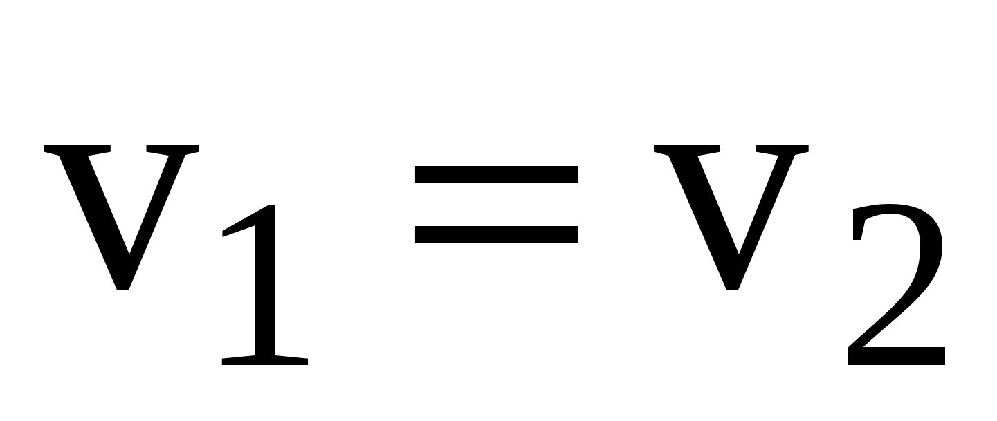 , That

Torque on shaft 1  (Nm), where [N]-W
 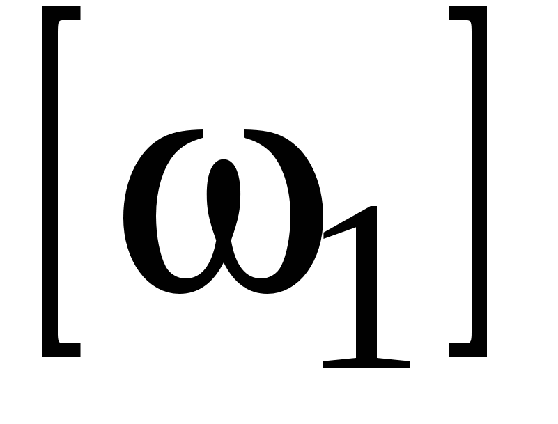 -rad/s
Torque on shaft 2  (Nm)
(Nm)
Dividing M 2 by M 1, we get 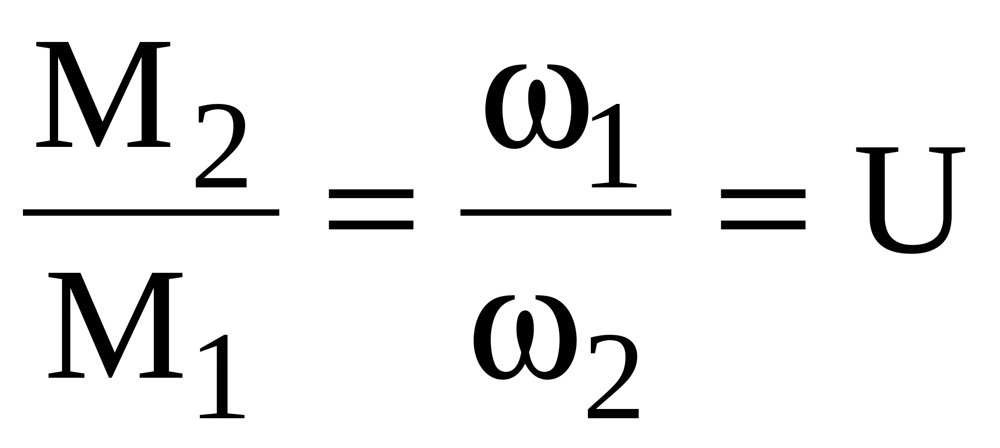 -gear ratio
Combining the outputs of the gear ratio values, we find

^ Forces acting in the meshing of spur teeth
cylindrical gears.
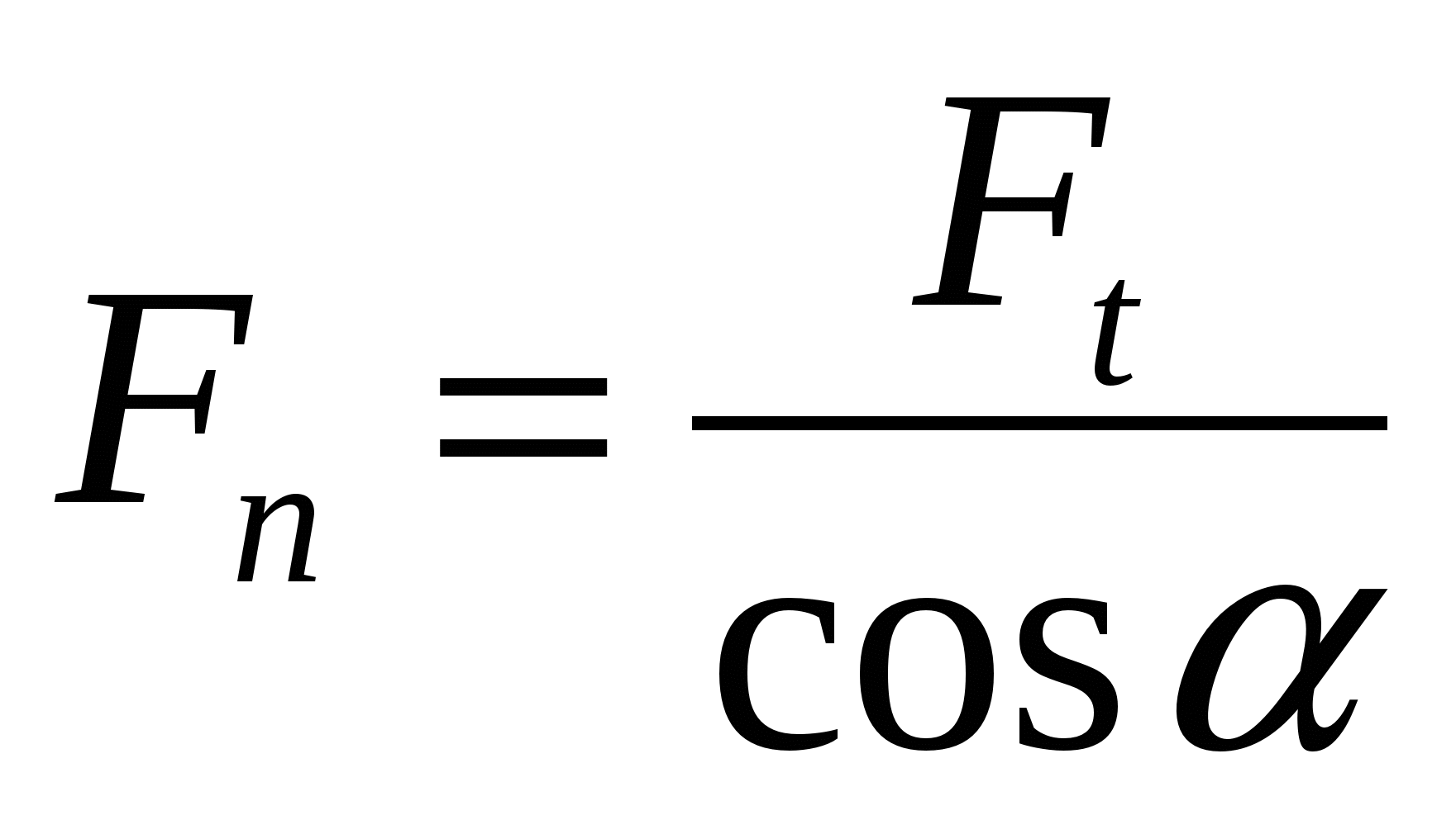
Since the friction forces between the teeth are small, the pressure force between them Fn can be considered directed along the general normal to the contacting surfaces of the teeth, i.e. along the engagement line. The forces acting in the gearing are usually applied at the gearing pole. In this case, the normal force (pressure force) Fn transferred to the pole and decomposed into circumferential and radial forces.
R  radial force F r ,
acting on the gear wheel is determined by the formula
  , where =20 engagement angle.
The circumferential force is  .
.
Pressure force between teeth of spur gear
^ Basic geometric parameters straight teeth cylindrical gears.
The main gear parameter is the module m. The module values are standardized in the range of 0.05 to 100 mm. . The module is measured in mm. . The magnitude of the module, expressed in terms of steps, is equal to
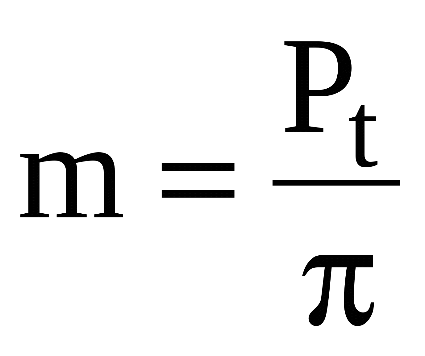
P t - circumferential pitch along the pitch circle - the distance between the same profiles of adjacent teeth.
Parameters related to the pitch surface or circle are not assigned an index. z 1 and z 2 - the number of teeth of the gear and wheel. Diameter of the pitch circle (along which the tool is rolled when cutting)

In gears without displacement (x = 0), the diameters of the initial circles (along which a pair of gears roll during rotation without sliding) coincide with the pitch circles


In gears without offset or with x 1 =-x 2 or x =0 y=0 y- equalization bias coefficient.
Center distance

For wheels without offset
the height of the tooth head h a is taken equal to the modulus
The height of the tooth stem h f is assumed to be equal to
h f = 
Tooth height h= 
Protrusion circle diameter
Diameter of the circle of the depressions
^ Materials and designs of gears.
The main materials are heat-treated steels. They provide sufficient contact and bending strength of the teeth. Distinguish between: gears with hardness  HB 350 - normalized, improved or hardened and gears with hardness HB 350 - hardened, nitrided, case-hardened.
Finish cutting of wheel teeth with a hardness of HB 350 is carried out after heat treatment. Receive high degree accuracy without the use of expensive finishing operations (grinding, lapping). Such wheels wear in well and are not subject to brittle fracture under dynamic loads. They are widely used in light and medium-loaded transmissions.
The use of high-hard materials is a great reserve for increasing the load capacity of gears.
Plastics are used in high-speed, light-loaded gears.
Study the design of gear wheels yourself.
^ The process of load transfer in an involute spur gearing.
End overlap coefficient .
The contact of the next drive wheel tooth with the driven wheel tooth begins at the stem of the drive tooth and at the top of the driven tooth (see poster gearing). Straight teeth mesh along their entire length at once. To ensure continuity of transmission of rotation to the driven shaft, before one pair of teeth disengages, the next pair of teeth must come into contact. This condition is ensured when the overlap coefficient - >1 - is the ratio of the arc of engagement (the arc through which the wheels rotate during the contact time of a given pair of teeth) to the pitch along this arc. In a spur gear, the load is transferred instantly from two teeth to one or from one to two. This phenomenon is accompanied by shocks and noise.

The picture of the load distribution along the tooth profile is as follows:
those. in the zone of uniform engagement (in the middle of the tooth or in the area of the engagement pole), the tooth transmits the full load, and in zones of two paired engagement approximately half the load. The size of the zone depends on the end overlap coefficient - for small-module wheels it is larger.
^ Manufacturing accuracy and its impact on transmission quality.
The quality of the transmission is associated with manufacturing errors of gears and other parts (housings, bearings and shafts).
Errors in the manufacture of gears: - errors in the pitch and shape of the teeth profile.
The accuracy of manufacturing gears is regulated by the State Standard, which provides for 12 degrees of accuracy, each of which is characterized by three indicators - the standard of kinematic accuracy, the standard of smooth operation, and the standard of tooth contact.
The degree of accuracy is selected depending on the purpose and operating conditions of the transmission. The most common are 6, 7, and 8 degrees of accuracy. (6 - high-precision, spur - V
^ Contact stresses and contact strength.
Contact stresses are formed at the point of contact of two bodies in cases where the dimensions of the contact area are small compared to the dimensions of the bodies (compression of two balls, a ball and a plane, two cylinders, etc.)
For example, compression of two cylinders: Under load, linear contact becomes contact along a narrow area
The points of maximum contact stresses n are located along the longitudinal axis of symmetry of the contact area:
![]()
For structural metals -Poison's ratio = 0.25 ...0.35. Take 1 = 2 =0.3

n =0.418,
Where E pr =  - reduced modulus of elasticity;
  - reduced radius of curvature.
Contact stresses are variable: each point is loaded only during the period of passage of the contact zone and is free from stress during the rest of the cylinder rotation. Variable contact stresses cause fatigue of the surface layers of parts.
^ CALCULATION OF TEETH STRENGTH BY CONTACT STRESSES .
Contact stresses n are formed at the point of contact between bodies, when the size of the contact area is small compared to the size of the bodies.
The contact of the teeth can be considered as the contact of two cylinders with radii 1 and 2. Contact stresses are determined from the Hertz formula
 ()
()
For spur gears
Where q is the design load distributed along the tooth contact line, that is, the load per unit length contact line;

F n - normal force in engagement (pressure force);
K n - design load coefficient;
b w - length of the contact line (length of the wheel tooth).
From previous material
 F t - circumferential force;
 E pr - drive modulus of elasticity for wheel materials.
Design load coefficient,
Where K n is the load concentration coefficient, which takes into account the concentration or uneven distribution of load along the length of the tooth associated with the deformation of shafts, housings, supports and the gears themselves, as well as gear manufacturing errors.
KH values are estimated approximately from graphs compiled on the basis of calculations and operating practice. With a constant load HB 350 and v 15 ms, K =1 can be taken.
K n v – dynamic load coefficient; takes into account the influence of variability of instantaneous values gear ratio and essentially depends on the peripheral speed. Calculating the value of K Hv is no less complicated than K H - it can be approximately taken from the table depending on v, the degree of accuracy and hardness of the tooth surface.
Thus, taking into account  can be written down

pr – reduced radius of curvature.
![]() ,
,
where, based on the figure, are the radii of curvature (for internal gearing) of the involute teeth at the point of contact.
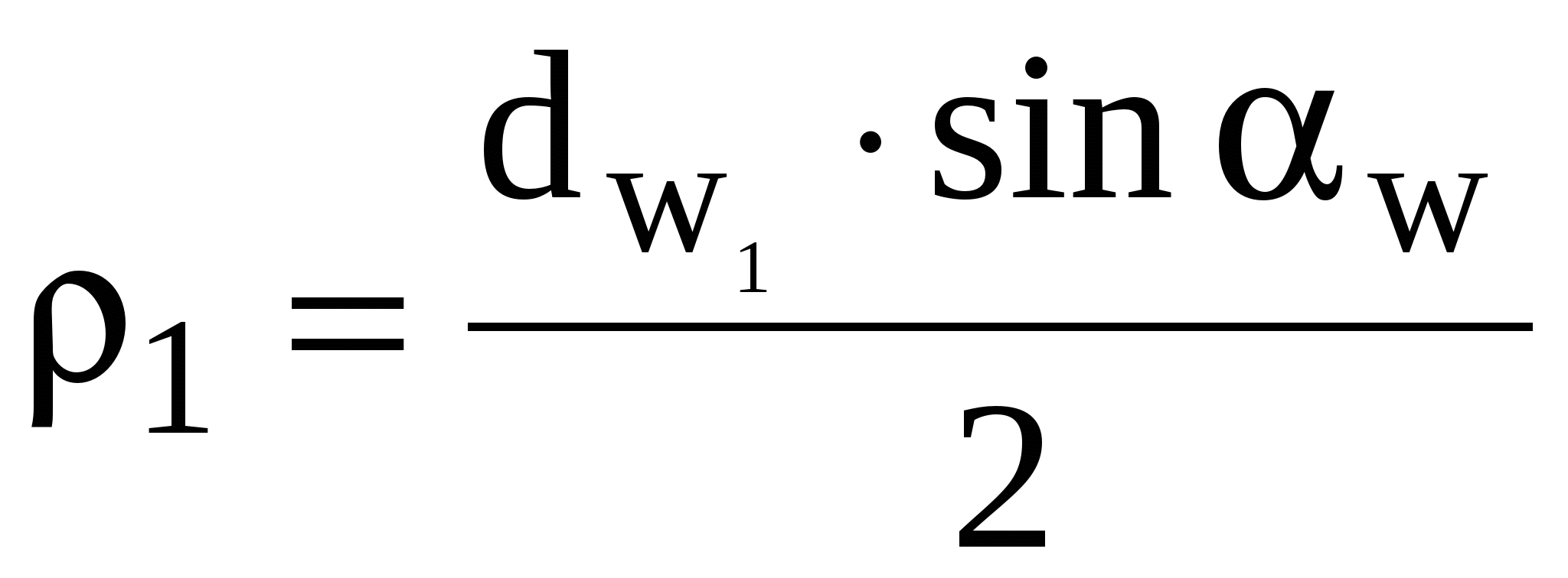

and taking into account
 , because

Substituting into formula () and replacing  , we get
 ()
()
The calculation is performed for the one of the wheels of the pair that has the lower permissible voltage n .
Formula () is used for verification calculations when all the necessary dimensions and other parameters are known. During the design calculation, it is necessary to determine the dimensions of the transmission according to the given main characteristics: torque T 1 and T 2 and gear ratio.
For the same purpose, formula () is solved with respect to d 1 or a. (Unknown parameters are approximately specified or selected according to recommendations.)
In our case w 20 ; dw =d 1; K n v =1.15 (the average value is taken, since v is unknown); denote 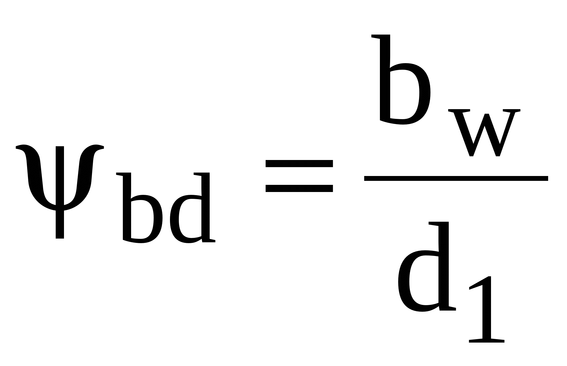 and solve for d 1
![]() .
.
When solving for a, replace T 1 =T 2 U;  And
And 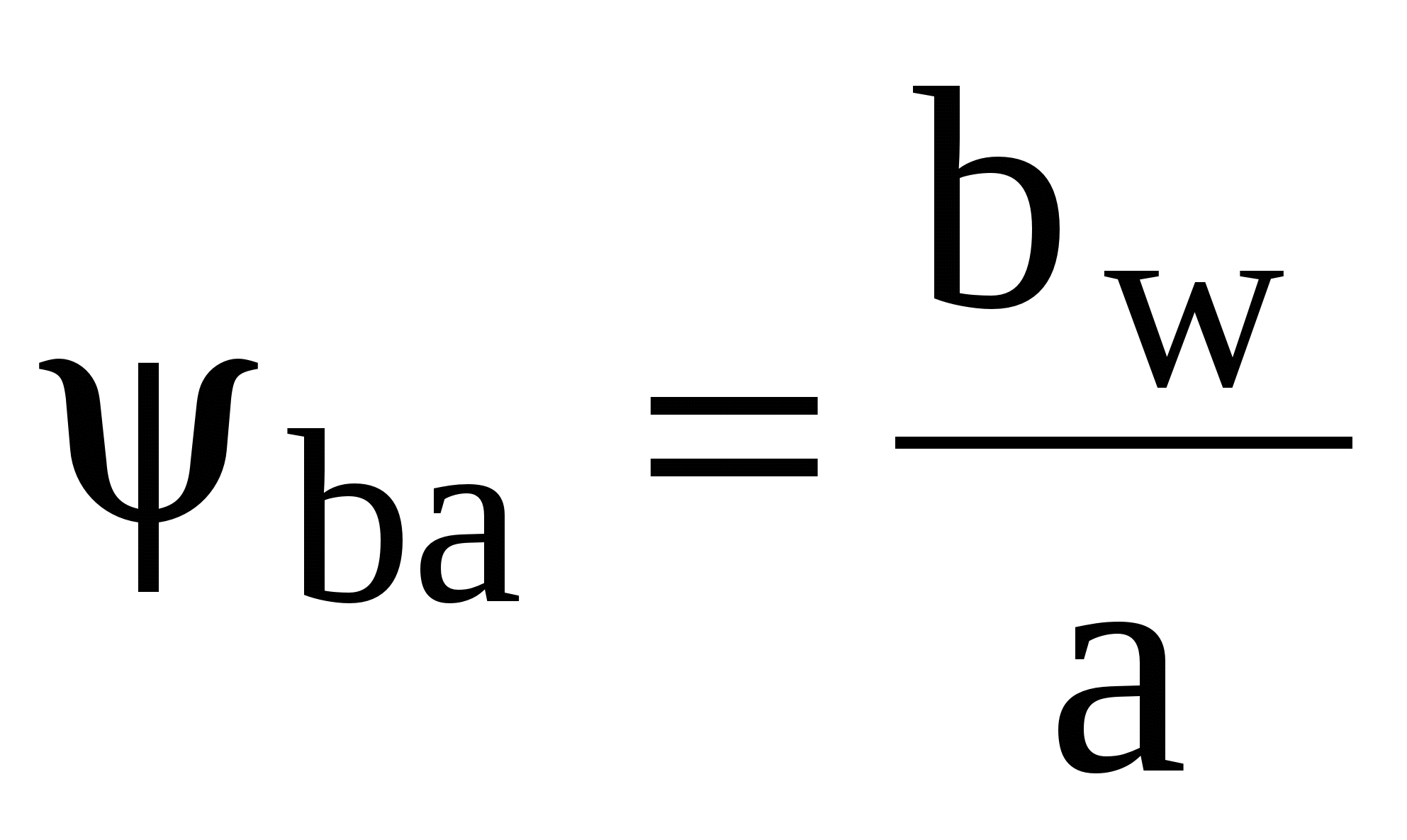 we get
 (W) .
(W) .
Estimated value“a” is rounded according to a standard series of numbers.
^
Calculation of gear teeth on
bending endurance.
Maximum stresses of the most dangerous section


and taking into account that 
we obtain a formula that is used to perform a test calculation for bending of straight teeth of cylindrical gears
 (+) ,
(+) ,
where y is the tooth shape coefficient, characterizing the position of the most dangerous section of the tooth, a dimensionless value (it depends on the shape of the teeth, the number of teeth and the displacement coefficient of the original contour). Determined depending on the equivalent number of teeth  given for helical gears (according to the table).

K F – load factor when calculating bending endurance;
K F - load distribution coefficient. When calculating spur gears for bending endurance, K F =1; for helical and chevron gears the values of K F at 0 depend on the degree of accuracy (0.72 at the 6th degree and 1.00 at the 9th degree).
K F - load concentration factor;
K F - dynamic load coefficient.

The resulting module value is rounded to the nearest in accordance with the preferred series of modules.
The calculation is carried out for the object (wheel or gear) whose product F y is less. The gear and wheel will be of equal strength in terms of bending stress if the condition is met  .
.
^ Calculation procedure for spur gears
for strength.
Strength calculations for spur and helical cylindrical gears are standardized by GOST 21354-75.
Open and closed passes are calculated differently:
When calculating closed gears, the design calculation is based on contact stresses. From it the main dimensions of the transmission are determined. Calculation based on bending stresses – verification.
The calculation is carried out in the following sequence: 
^ Working conditions of a tooth in mesh.
When a gear drive operates, a pressure force arises between the teeth of the mating gears. F n(Fig.), directed along the line of engagement. In addition, friction force is generated from the sliding of the teeth between them. F tr =F n f, where f is the friction coefficient. Force F tr small compared to strength F n , therefore, when deriving calculation formulas, it is not taken into account, i.e., it is assumed that the interaction force between the teeth is directed normal to their profiles. Under the influence of forces, the teeth are in a complex stressed state. Their performance is influenced by bending stresses F in the cross sections of the teeth and contact stresses H in the surface layers of the teeth. Both of these stresses, variable over time, can cause fatigue failure of the teeth or their working surfaces. Bending stresses cause tooth breakage, and contact stresses cause fatigue chipping of the surface layers of teeth. Contact stresses and friction in meshing are also associated with wear, jamming and other types of damage to tooth surfaces.

^ Types of destruction of gears.
All types of tooth surface damage are associated with contact stresses and friction.
Fatigue spalling from contact stresses is the main type of destruction of the tooth surface when the gear is well lubricated. The teeth are separated by a thin layer of oil, eliminating metal-to-metal contact. At the same time, tooth wear is small. The transmission operates for a long time until fatigue appears in the surface layers of the teeth. Small depressions appear on the surface, which then grow and turn into shells.
Chipping begins near the pole line on the legs of the teeth, where the load is transmitted by one pair of teeth, and the sliding and rolling of the teeth are directed so that the oil is pressed into the cracks and promotes chipping of metal particles.
Basic measures to prevent chipping:
endurance calculation based on contact stresses;
increasing the hardness of the material by heat treatment;
increasing the degree of precision in the manufacture of gears.
The strength of the tooth decreases due to its reduction cross section. This leads to tooth breakage.
Basic measures to prevent wear:
increasing the hardness and cleanliness of the tooth surface;
protection against abrasive particles;
the use of oils with chemically active additives.
Measures to prevent jamming are the same as against wear:
intensive cooling of the lubricant;
use of special extreme pressure oils.
Plastic shifts can be eliminated by increasing the hardness of the tooth material.
Peeling of the hard surface layer from nitrided, cemented and hardened tooth surfaces. This type of destruction is observed when the quality is insufficiently high. heat treatment when internal stresses are not relieved by tempering or when the fragile crust of the teeth does not have a sufficiently strong core underneath. Peeling is promoted by the action of large loads.
