The required electric motor power is determined by formula (7.1) or (7.3); the appropriate standard size is selected according to the table. 2.2. Since motors with different rotation speeds are suitable for the drive being calculated, you should consider several options and settle on the optimal one that corresponds to specific operating conditions. It should be taken into account that with an increase in rotation speed, the mass of the engine and its dimensions decrease, the cost decreases, but the working life also decreases. Therefore, for drives general purpose, unless there are special instructions, engines with rotation speeds of 1500 or 1000 rpm are preferred (respectively, the rotation speed at rated mode, taking into account 3% slip, n nom ≈ 1450 or 970 rpm).
p in = 60 v / πD (7.1)
Then determine the overall drive ratio
i = n nom / p in (7 .2)
and make a preliminary breakdown of it:
i = i 1 i 2….. i k (7.3)
where i 1,….., i k are the particular values of the gear ratios of each gear included in general scheme drive. During the design process, they are specified in accordance with the standards for the parameters of belt, chain, gear and worm gears.
Selecting the gear type. A connection between a machine shaft and an electric motor shaft is possible only in relatively rare cases when the rotation speeds of these shafts are the same, for example in drives of centrifugal pumps, fans, etc. If this condition is not met, then an overdrive or downshift is required to drive the machine.
The optimal type of transmission is determined taking into account a number of factors: operating conditions, the nature of load changes during operation, a given service life, safety requirements, ease of maintenance and repair, the cost of the drive and its installation.
Depending on the specific conditions, the designer designing a mechanical drive device considers options for using gears various types- gear, worm, belt, chain, friction and their appropriate combinations.
The design of drive devices should begin with kinematic calculations. The initial data required for the calculation may be the following indicators: the nominal torque T on the shaft of the driven machine, its angular velocity (or rotational speed), a graph of changes in load and rotational speed for a certain period. For conveyor drives, instead of the rotational speed of the drive shaft, the speed of the belt or chain and, accordingly, the diameter of the drum or sprocket are often indicated, and instead of the torque on the drive shaft, the circumferential force F is indicated. From these data, it is easy to determine the values of the torque and rotational speed. Next, having previously specified the rotational speed of the electric motor shaft (preferably from a number of synchronous frequencies n c = 1000; 1500; 3000 rpm), the values of gear ratios are calculated for several drive options.
Analyzing the obtained values, several options for the drive layout are outlined, including mechanical transmissions various types. Kinematic diagrams of drives should be considered as preliminary, subject to clarification in the process of further design.
Motor selection
To select an electric motor, the operating conditions must be known (load schedule, temperature and humidity environment etc.), required power and shaft speed. In accordance with these data, an electric motor is selected from the catalog and checked for heating under steady-state and transient conditions and under short-term overload.
In a number of cases, the selection of an electric motor is simplified: 1) with a long-term constant or slightly varying load, a heating test is not necessary, since the manufacturer performed it for the specified conditions and guarantees long work at nominal mode; 2) for intermittent short-term operating mode, select a motor with an increased starting torque, taking into account the duration of switching on (PV, %); 3) if the machine for which the drive is being designed often turns on and off, has increased static resistance and significant dynamic torque during the start-up period, then the selected electric motor should be checked by the value of the starting torque T start.
The first case of loading an electric motor covers a large number of types of mechanical drives - for fans, pumps, compressors, conveyors, conveyors, etc. The second case of loading is typical for drives of winches, cranes, lifts, etc.
In projects carried out in the machine parts course, drives for machines included in the first group are mainly developed. Therefore, the electric motor selected from the catalog does not need to be checked for heating. The required electric motor power P (W) is determined by the calculated rated load [for example, for conveyors and conveyors - by traction force (H) and belt speed v (m/s)]. Then the required power
P = Fv / η (8.1)
where η is the efficiency coefficient of the entire drive, equal to the product of the partial efficiency of the gears included in the drive;
η = η 1 η 2 η k (8.2)
The average gear efficiency values are given in table. 8.1 (taking into account friction losses in bearings); it also indicates the average values of gear ratios, which can be taken as indicative when completing course projects.
If the initial data for designing the drive indicates the values of the torque T (N * m) on the drive shaft and the angular velocity of this shaft ω (rad/s), then the required electric motor power, W
P = T ω / η (8.3)
Based on the found engine power, the type most suitable for specific operating conditions is determined.
Table 8.1
Values of efficiency and gear ratios
The industry produces a large number of electric motors for all sectors of the national economy. Based on the type of current, they are divided into the following types.
1. Engines direct current; they allow smooth regulation angular velocity shaft, provide smooth start, braking and reversing; Designed mainly for drives of electric vehicles, cranes, lifting systems, etc.
2. Single phase A synchronous motors low power, used in drives of household mechanisms.
3. Three-phase synchronous motors, the rotation speed of which does not depend on the load; characterized by high mechanical reliability, low sensitivity to mains voltage fluctuations; They are used mainly in high-power installations.
4. Three-phase asynchronous motors, most common in various sectors of the national economy; their advantages compared to engines of other types: simplicity of design, lower cost, higher operational reliability. When completing course projects, you should choose these motors for drives.
At nominal mode, the average value s ≈ 3 ÷ 5%. IN the engine starting period, the torque on its shaft changes from T start to T max, the rotation speed increases from 0 to n cr. Point T max n cr is critical; operation in this mode is unacceptable, because the engine overheats quickly. When the load decreases from T max to T nom, i.e. when transitioning to the nominal steady state, the rotation speed increases to n nom. With a further decrease in load, the rotation speed increases and at T = 0 reaches the value n s, when the slip x = 0.
The engine starts at s = 1 (or 100%), when n = 0. The point S cr, T max is critical, the engine must pass through it without the slightest delay. The section between the maximum and starting torques is almost linear: the torque is proportional to the sliding. At s nom, the engine develops rated torque and can be operated in this mode for a long time. At S= 0, torque T is also zero, and the rotation speed increases to n s (rpm), determined by the formula:
where f is the current frequency equal to 50 periods in 1 s; p - number of pairs of poles. As a rule, motors for mechanical drives are selected with a number of pole pairs from 1 to 4 (Table 8.2).
Table 8.2
Determination of the number of pole pairs
These are the approximate values of n nom and should be taken into account when determining the gear ratios of the designed drives.
Three-phase asynchronous squirrel-cage motors of a single series 4A for general purpose for continuous operation are available in two versions: protected motors with a power of 15 - 400 kW and enclosed blown motors with a power of 0.06-315 kW. These motors are more reliable and easier to operate than protected motors, so it is recommended to choose them for general purpose drives.
Conclusion
Based on materials course work the following conclusions can be drawn:
1. Completed a breakdown of the total gear ratio step by step
2. Justified the choice of the main parameters of gearboxes
3. Justified the choice of steel grades for gears
4. Determined permissible stresses
5. Determined the main parameters cylindrical gears
6. Described cylindrical gears. Brief information in geometry and kinematics
7. Described the drive gear ratio
8. Justified the choice of electric motor
Bibliography
1. Babkin I.A. Competitiveness as a factor determining the strategy of an enterprise // Economics and competitiveness of Russia: Interuniversity collection scientific works. Vol. No. 6. - St. Petersburg: Polytechnic Publishing House. University, 2004.
2. Bakanov M.I. Sheremet A.D. Theory economic analysis. - N.: Textbook Finance and Statistics, 1997.
3. Beiselman R.D. and others. Rolling bearings. – M.: Mashinostroenie, 1975.
4. Birger I.A., Iosilevich G.B., Threaded connections. - M.: "Mechanical Engineering" 1973.-256 p.
5. Belyakov V.M., Zharkov M.S., Fedorov V.V., Yankovsky V.V. Gears rolling stock: Tutorial for students. Kuibyshev: KIIT, 1990.
6. Bogdanov A.I. Strategic management of scientific and technological progress at an enterprise (association). - M.: VAF, 1991.
7. Shafts and axles. Design and calculation / Ed. Sørensen. M.: Mechanical Engineering, 1980.
8. Guzenkov P.G. Theory of mechanisms and machines, machine details. Guidelines and tasks for test papers. "Higher School", 1966.- 93 p.
9. Machine parts in examples and problems: Textbook for universities / Ed. Nichiporchika S.N. – Minsk: Higher School, 1981.
10. . Machine parts: Handbook / Ed. Acherkana.N.S. In 3 vols. – M.: Mashinostroenie, 1968-1969.
11. Machine parts: Atlas of structures / Ed. Reshetova D.N. – M.: Mechanical Engineering, 1988.
12. Machine dynamics and machine control: Handbook / Edited by G.V. Kreinin – M.: Mashinostroenie, 1988.
13. Ignatovich A.M., Markov A.N., Machine parts. Methodological instructions and test tasks. - M.: "Higher School", 1975.-95 p.
14. Ivanov M.N. Machine parts. - M.: "Higher School", 1991. - 383 p.
15. Information revolution: science, economics, technology - M.: INION, 1993. - 202 p.
16. Itskovich G.M. Chernavsky S.A. and others. Collection of problems and examples of calculations for the course of machine parts. - M. "Machine Building", 1975. 286 p.
17. Klyachkin N.L. Calculation of group threaded connections. M.:
18. Lyubushin M.P., Leshcheva V.B., Dyakova V.G. Analysis of the financial and economic activities of the enterprise. Textbook for universities. – M.: UNITY-DANA, 1999.
19. Practical guide. - M.: Finpress, 1998. - 272 p.
20. "Mechanical Engineering", 1972. - 386 p.
21. Maksimova N. S. On reforming interbudgetary relations in Russian Federation//Finance, 1998, No. 6.
22. Maksimkina E.A., Loskutova E.E., Dorofeeva V.V. Competitiveness of a pharmaceutical organization in market conditions. - M.: MCFR, 1999. - 256 p.
23. Nikolaev G.A. and others. Design of welded structures in mechanical engineering. - M.: "Machine Building", 1975. - 212 p.
24. S.N. Nichiporchik, M.I. Korzhentsevsky, V.F. Kalachev and others. Machine parts in examples and problems. - 2nd ed. - Mn.: "Higher School", 1981. - 432 p. .
25. Serensen S.V., Kogaev V.P., Shneiderovich R.M. Load-bearing capacity and strength calculations of machine parts. - M "Mechanical Engineering". 1983.- 343 s
26. Tarabasov N.D., Uchaev P.N. Design of parts and assemblies of machine-building structures: Directory. – M.: Mashinostroenie, 1983.
27. Friction, wear, lubrication: Directory / V.V. Alisin et al. – M.: Mashinostroenie, 1980.
28. Chernavsky S.A. Sliding bearings. – M.: Mashgiz, 1963.
29. Chernavsky S.A., Bokov K.N., Chernin I.M. and others. Course design of machine parts: Textbook. - M.: Mashinostroenie, 1988. -416 p.
30. Chernavsky S.A. Course design of machine parts: Textbook for technical schools. – M.: Mashinostroenie, 1980. – 351 p.
Application
Annex 1
Mechanical properties steels
| steel grade | Diameter D, mm | Width S, mm | NV cores | HRC surfaces | σ B | σ T | Heat treatment |
| MPa | |||||||
| Any | Any | 163-192 | - | Normalization | |||
| » | » | 179-207 | - | » | |||
| 235-262 | - | Improvement | |||||
| 269-302 | - | » | |||||
| 40X | 235-262 | - | » | ||||
| 40X | 269-302 | - | » | ||||
| 40X | 269-302 | 45-50 | Improvement + | ||||
| HDTV hardening | |||||||
| 35ХМ | 235-262 | - | Improvement | ||||
| 35ХМ | 269-302 | - | » | ||||
| 35ХМ | 269-302 | 48-53 | Improvement + | ||||
| HDTV hardening | |||||||
| 40ХН | 235-262 | - | Improvement | ||||
| 40ХН | 269-302 | - | » | ||||
| 40ХН | 269-302 | 48-53 | Improvement + | ||||
| HDTV hardening | |||||||
| 20ХН2М | 300 - 400 | 56-63 | Improvement + | ||||
| cementation + | |||||||
| hardening | |||||||
| 18ХГТ | 300-400 | 56-63 | Same | ||||
| 12ХНЗА | 300 - 400 | 56-63 | » | ||||
| 25ХГМ | 300 -400 | 56-63 | » | ||||
| 4QXH2MA | 269-302 | 50-56 | Improvement + | ||||
| nitriding | |||||||
| 35L | Any | Any | 163-207 | - | Normalization | ||
| 45L | 207-235 | - | Improvement | ||||
| 40GL | 235-262 | - | » |
Appendix 2
The calculation applies to steel spur, helical and chevron gears gearboxes, spur open gears and rack and pinion spur gears, subject to following conditions:
a) for gearboxes:
1) the shafts rest on rolling bearings;
2) the housing is protected from the penetration of dirt and water and has sufficient rigidity;
3) the teeth are lubricated with oil;
4) the environment is chemically non-aggressive;
5) the oil temperature in the housing is not higher than 95 °C;
b) degree of accuracy according to the standards of smoothness and contact 6-9 - according to GOST 1643 - 81;
7) peripheral speed gear wheels- up to 16 m/s;
8) parameter of the roughness of the working surfaces of the teeth Ra≤ 2.5 µm;
9) initial contour according to GOST 13755-81;
b) for open gears:
1) the teeth are lubricated with grease;
2) degree of accuracy according to contact standards 9-10 according to GOST 1643-81;
3) spur gears;
4) peripheral speed up to 2 m/s;
5) wheel width - no more than 10 modules. Basic designations:
A- interaxial distance, mm;
b- width gear wheel; mm;
d- diameter, mm;
F- force, N;
i- gear ratio;
TO- coefficient;
K d- durability factor;
K B- equivalence coefficient;
Kv - dynamic factor:
To a- load distribution coefficient:
K β - load concentration factor;
L- life time;
l- length, mm;
M - bending moment, N m;
T- fatigue curve indicator;
T- module, mm;
N- number of cycles of voltage change (operation);
N G- voltage base;
P - rotation speed, min -1;
R - Power, W;
T - torque, N mm;
t-time, s;
And- gear ratio of one pair of gears;
v- peripheral speed, m/s;
X - mode coefficient:
X - displacement coefficient;
Yf- tooth shape coefficient;
Yβ - tooth inclination coefficient;
Z- number of teeth;
α - engagement angle;
Based on the known speed values at the input n and n outputs, we determine the total gear ratio of the gearbox using the formula:
Substituting the values of n and n outputs obtained in the previous paragraph, we obtain:

Determination of the number of steps
Since the specification for determining the number of stages specifies the mass minimization criterion, according to this we have the formula
 (3), where
k- estimated number of EMF stages;
i 0 - overall gear ratio, i 0 =225;
With 2 - coefficient determined for equal-strength bending gears according to the formula:
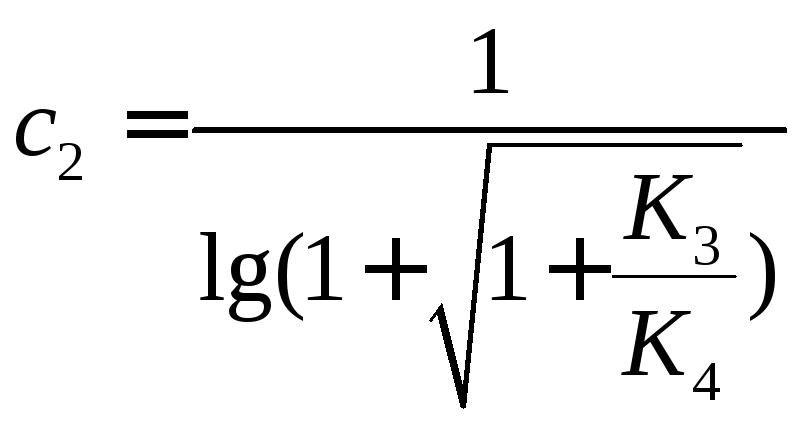 , Where
K 3 , K 4 – coefficients that take into account the dependence of the gear mass on the design. Selected from the table. K 3 =0.5, K 4 =4.
Substituting the values in (3) we get:
Rounding to the nearest larger integer, we find that the number of gear stages is k=4.
Distribution of the total gear ratio by stages
Table 1
Since the number of teeth is selected from the recommended standard row, the resulting gear ratio may differ slightly from the calculated one. The error (Δi) of the actual gear ratio from the calculated one should not exceed 10%, where  .
.
The actual gear ratio i actual is found using the formula:
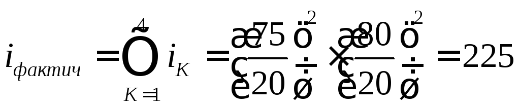 .
.
We calculate the error of the gear ratio:
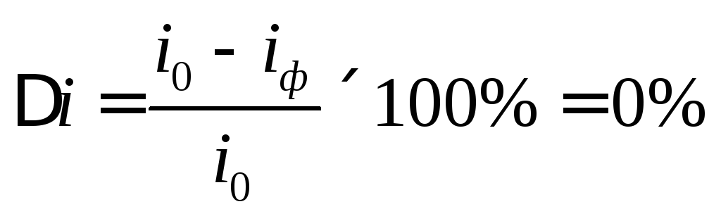
Consequently, the choice of the number of teeth of wheels and gears was made correctly.
The kinematic diagram of the gearbox is shown in Fig. 1.
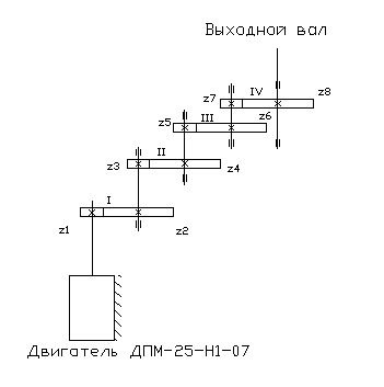
Fig.1. Kinematic diagram of EMF
Power calculation em Check calculation of the selected motor for static load
Since at this stage of design the kinematic diagram of the EMF is known, then from the ratio of moment reduction:
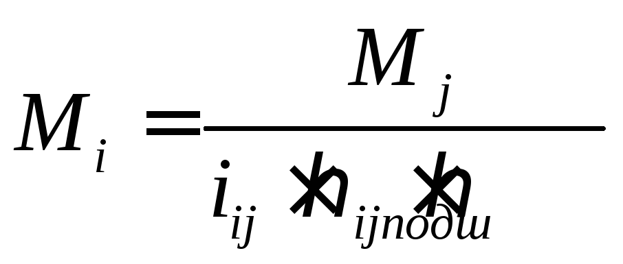 (4), where
M i ,M i– load moment on the i-th and j-th shafts;
i ij– gear ratio of the i-th and j-th shaft;
η ij– transmission efficiency, η ij =0.98;
η subsh– efficiency of bearings in which the drive shaft is installed, η subsh =0.99.
Since at the moment of starting the engine it is necessary to take into account the inertia of the engine and the load, it is necessary that the engine provides the required angular acceleration of the load. Taking into account the dynamic component, the following moment applies to the output shaft:
M Σ = M n + J n n =0.35+0.2*10=2.35 (N*m)
In order to check the correctness of the choice of motor, it is necessary to bring the torque on the output shaft to the motor shaft according to formula (4) for each shaft, starting from the output one, and compare the starting torque of the motor with the reduced torque.
We carry out the calculation sequentially to the motor shaft:

Let's perform a preliminary check of the correct choice of engine:

According to passport data M start=11.8·10 -3 N·m, that is, 11.8≥11.8 – correct => the engine is selected correctly. That is, the selected engine will be able to provide the required angular acceleration of the load at start.
Determination of the engagement modulus
The engagement modulus is determined from the calculation of teeth strength (flexural and contact). Since EMF design assumes open type gears, then the calculation of teeth for bending is a design one.
During the verification calculation, based on the known geometry of the teeth and given loads, the effective contact stresses σ n are determined and the condition σ n ≤ [σ n ] is checked.
The bending strength calculation is carried out for the most loaded gear stage, i.e. in our case for the stage Z 8 -Z 7. In this case, the module is determined by the less durable wheel of a geared elementary pair by the ratio:
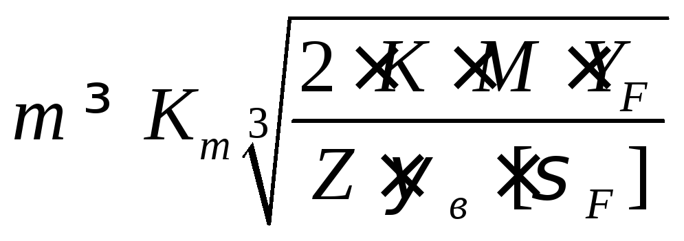 (5), where
m – spur gear module;
K – design load coefficient, K=1.1...1.5 (selected according to ), select the value K=1.3;
M – torque acting on the calculated wheel [Nm],
Y F – tooth shape coefficient, selected from the table, in our case Y F =3.73;
ψ in – gear shape coefficient, for small-module gears ψ in =3...16 (according to ), choose ψ in =6;
 – permissible stress when calculating teeth for bending [MPa];
Z – number of teeth of the calculated wheel.
If, when determining the module m using formula (5), it gave the value< 0.3 мм, то, исходя из конструктивных соображений, модуль принимают равным 0.3 мм.
We use stronger material for the gear. We select material from the recommended pairs:
Gears: steel 20X
Heat treatment: volumetric hardening (must be stronger)
= 7.85 g/cm 3
in = 850 MPa – tensile strength
t = 630 MPa – yield strength
Wheels: steel 50
Heat treatment: surface hardening
= 7.85 g/cm 3
in = 800 MPa – tensile strength
t = 590 MPa – yield strength
[σ F ]=  , Where
σ FR – bending endurance limit;
K FC – coefficient taking into account the wheel loading cycle;
K FL – durability coefficient;
δ F – safety factor (since the operating condition is short-term, then δ F = 2.2);
K FC =1, for non-reversible gears.
KFL = 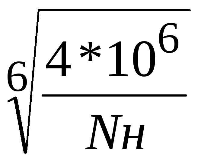 , Where
N Н – number of loading cycles
n – gear rotation speed, n=20 rpm,
c – the number of wheels that are simultaneously in mesh with the one being calculated, c = 1,
L – transmission service life, L=100 hours.
N Н =60·20·1·100=120000 revolutions
K FL = (4000000/120000)^1/6 = 1.794
Both gears and wheels have σ FR =550 MPa.
[σ F ]=  = 550 1 1.794/2.2 = 448.5 MPa
For gears, the values of Y f are greater than for wheels, and, therefore, the ratio Y f / [σ f ] is greater, so I carry out the calculation using the gear.
Substituting the data into formula (5) we get
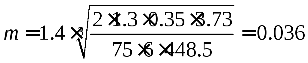
Based on design considerations, we assign the engagement modules for all gears to be equal to 0.3 mm.
Determination of permissible stresses for gears and wheels
[σ n ] =σ HR ·Z R ·Z V ·K HL 1.2 /δ H 12, where
σ HR – contact endurance limit of the tooth surface;
σ HR gears = 18·HRC+150 = 18·52+150 = 1086 MPa;
σ HR wheels = 17·HRC+200 = 17·48+200 = 1016 MPa;
Z R – roughness coefficient of mating surfaces, Z R =1;
Z V – coefficient taking into account the peripheral speed of the wheel, Z V =1;
δ H 12 – safety factor, δ H 12 = 1/2;
K HL – durability coefficient
KHL = 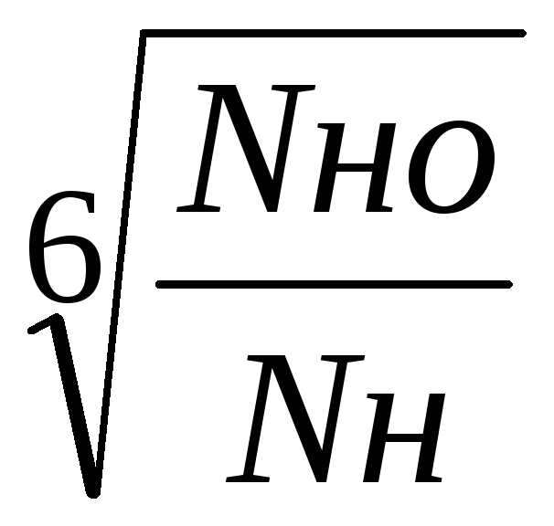 , Where
NH = 120000 rpm
N HO = 1.5*10 8 for gears hardened to HRC45...50
KHL = = 
[σ n ] gears = 1086 1 1 3.282/1.2 = 2970 MPa
[σ n ] wheels = 1016 1 1 3.282/1.2 = 2778 MPa
Therefore, the permissible contact stress
[σ n ] = 2778 MPa
Allowable bending stress
Sometimes, in a large flow of information (especially new information), it is very difficult to find some important details, to highlight the “grains of truth”. In this short article I will talk about gear ratios and the drive in general. This topic is very close to the topics covered in...
The drive is the engine and everything that is located and works between the engine shaft and the shaft of the working element (clutches, gearboxes, various gears). I think almost everyone understands what a “motor shaft” is. What a “working body shaft” is is probably not clear to many. The shaft of the working element is the shaft on which the element of the machine is fixed, which is driven into rotation by the entire drive with the required specified torque and rotational speed. This could be: a trolley (car) wheel, a belt conveyor drum, a chain conveyor sprocket, a winch drum, a pump shaft, a compressor shaft, and so on.
U– is the ratio of the engine shaft speed ndv to the rotational speed of the shaft of the working body of the machine npro.
U = ndoor / nro
Total drive ratio U Often in practice, calculations result in a fairly large number (more than ten, or even more than fifty), and it is not always possible to perform it in one gear due to various limitations, including power, strength and size. Therefore, the drive is made consisting of several gears connected in series with with their optimal gear ratios Ui. In this case, the total gear ratio U is found as the product of all gear ratios Ui included in the drive.
U =U1 *U2 *U3 *…Ui *…Un
Transmission ratio Ui– is the ratio of the transmission input shaft rotation speed nвхi to the rotational speed of the output shaft of this transmission nouti.
Ui = nin/nouti

When choosing, it is advisable to give preference to values close to the beginning of the range, that is, the minimum values.
The proposed table is just recommendations and not dogma! For example, if you assign chain transmission U=1.5, then this will not be an error! Of course, everything must have a justification. And perhaps this is better to reduce the cost of the entire drive U=1.5 “hide” inside the gear ratios of other gears, increasing them accordingly.
Optimization issues during design gear reducers paid a lot of attention by various scientists. Dunaev P.F., Snesarev G.A., Kudryavtsev V.N., Niberg N.Ya., Niemann G., Wolf W. and other well-known authors tried to simultaneously achieve equal strength of gear wheels, compactness of the gearbox as a whole, good conditions lubrication, reduced losses due to oil splashing, equal and high durability of all bearings, good shaft rigidity. Each of the authors, having proposed their own algorithm for dividing the gear ratio into gear stages, did not completely and unambiguously solve this controversial problem. It is very interesting and detailed about this in the article at: http://www.prikladmeh.ru/lect19.htm.
I'll add to the solution this issue a little more ambiguity... Let's look at another table in Excel.
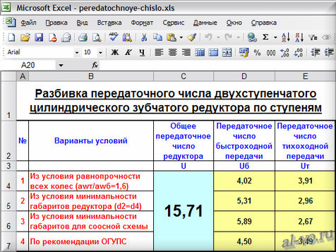
We set the value of the total gear ratio of the gearbox in the combined cell C4-7 U and read the calculation results in cells D4...D7 - Ub and in cells E4...E7 – UT, performed for four variants of different conditions.
The values given in the table are calculated using the formulas:
1. In cell D4: =H4*$C$4^2+I4*$C$4+J4 =4,02 Ub =a *U ^2+b *U +c
in cell E 4 : =$C$4/D4 =3.91 UT = U / Ub
in cell H4: a =-0,0016111374
in cell I 4: b =0,24831562
in cell J 4: c =0,51606736
2. In cell D5: =H5*$C$4^2+I5*$C$4+J5 =5.31 Ub =a *U ^2+b *U +c
in cell E 5 : =$C$4/D5 =2.96 UT = U / Ub
in cell H5: a =-0,0018801488
in cell I 5: b =0,26847174
in cell J 5: c =1,5527345
3. In cell D6: =H6*$C$4^2+I6*$C$4+J6 =5.89 Ub =a *U ^2+b *U +c
in cell E 6 : =$C$4/D6 =2.67 UT = U / Ub
in cell H 6: a =-0,0018801488
in cell I 6: b =0,26847174
in cell J6: c =1,5527345
4. In cell D 7: =C4/E7 =4.50 Ub = U / UT
in cell E 7: =0.88*C4^0.5 =3.49 UT =0,88* U ^0,5
In conclusion, I dare to recommend: do not design a single-stage gear helical gearbox with gear ratio U>6…7, two-stage – with U>35…40, three-stage – with U>140…150.
This concludes a brief excursion into the topics “How to optimally “split” the drive gear ratio into stages?” and “How to choose a gear ratio?” completed.
Dear readers, subscribe to receive announcements of my blog articles. The window with the button is at the top of the page. If you don't like it, you can always unsubscribe.