Every evening you have to turn it on, and every morning you have to turn it off. And if in good weather You can somehow put up with this, sometimes in rain or snow... Therefore, the idea arises to automate the switching on and off of lamps. This is what a photo relay for street lighting does.
This device has a lot of names. In the literature you will find the name light-control switch or light-sensitive machine, and when communicating you can hear it as an illumination or light sensor, photosensor, twilight/twilight sensor or day/night. Perhaps there are others. But all this is about one device that turns on the lighting at dusk and turns it off at dawn.
Photo relays are made on the basis of a photoresistor or phototransistor, which change their parameters when the illumination changes. As long as enough light falls on them, the power circuit remains open. As darkness falls, the parameters of the photoresistor/transistor change and, at a certain value (set by settings), the circuit closes. In the morning, the process is exactly the opposite: when the illumination reaches a certain level, the power circuit is broken.
Specifications
First of all, you need to decide whether you want a photo relay for street lighting with an external or built-in light sensor. The remote sensor has small sizes and it is easier to protect it from backlighting; the device itself can be placed in the house, for example, in a panel. There are even models for DIN rail. A photo relay with a built-in light sensor can be placed near the lamp. It is only important to choose a place so that the light from the lamp does not affect the photosensor. This option is more convenient, for example, for .

Performance characteristics
Having decided on the type of sensor, we move on to the technical parameters:

To select a photo relay for street lighting, these characteristics are required. Their correct choice determines the performance of the device. But there are still some parameters that affect the correct operation of the device.
Customization options
There are several adjustments that allow you to customize the operation of the photo relay in each specific case. The problem is that the settings are made manually by turning the desired regulator and achieving absolutely identical parameters for several devices is unrealistic. There are always some differences in their work.

Using these settings, you can make the operation of the photo relay to automatically turn on the lighting of the area comfortable and eliminate false alarms.
Where to put
Choosing the right place to install a photo relay for street lighting is quite a quest. Several requirements must be taken into account:

With all this, the installation height of the photo relay is at the level of 1.8-2 m. This will make it possible to adjust the parameters “from the ground”. You can go higher, but you will need a stepladder/ladder or a chair/stool.
As you can imagine, finding such a place is not easy. There are several tricks that make the solution easier:

And another piece of advice from practice: it’s easier to adjust the operating parameters if the light sensor of the photo relay is located on the eastern or western wall. But only if there are no brightly glowing objects there. In this case, it is best to choose the side where the “exposure” is least.
Types of photo relay
As already mentioned, there is a photo relay with a built-in and remote light sensor. In addition, you can find the following varieties:

If you need one of the functions described above, it is not at all necessary to buy a photo relay with a motion sensor or timer. You can install a regular sensor and connect it in series with it required device(motion sensor or timer). The functions will be the same, and repairs and replacement will cost less. If one of the parts in a photo relay with additional functions fails, you will have to change the device completely, and this option costs more than its “no frills” counterpart.
Connection diagrams for photo relays for street lighting
The purpose of a photo relay for street lighting is to supply power at nightfall and turn it off at dawn. That is, it is a kind of switch, only instead of a key there is a photosensitive element installed in it. Therefore, its connection diagram is similar: a phase is supplied to the photo relay, removed from its outputs and supplied to lamps or a group of lamps.

The simplest case is a diagram for connecting a photo relay to a lantern
Since the photo relay also requires power to operate, a zero is applied to the corresponding contacts; it is advisable to also connect the ground.
As we said earlier, you need to select a photo relay based on the power of the connected load. But one pattern is observed: with increasing power, prices increase significantly. To save money, you can supply power not through a photo relay, but through. It is designed for frequent power on/off, and can also be used to connect power using a light-sensitive element with a small connected load. In fact, it only turns on the magnetic starter, so only its power consumption is taken into account. And a powerful load can be connected to the terminals of the magnetic starter.

If, in addition to the day/night sensor, you also need to connect a timer or motion sensor, they are placed in series after the lighting relay. The order in which the movement/timer is set is not important.

If a motion sensor or timer is not needed, simply remove them from the circuit. She remains operational.
Installation and configuration
A photo relay with a built-in photosensor has three wires coming out of the housing. They are always connected the same way:
- Red goes to the load - a lantern, light bulbs, lamps.
- The brown or black wire is connected to the phase taken from the panel.
- The neutral from the bus with the “working zero” from the panel is connected to the blue one.

It is also advisable to ground the device by connecting it to the appropriate terminal on the housing. The wire cross-section is selected depending on the power of the connected load.
The relay is configured after it is installed and connected. When twilight sets in, wait until you are in a state where you would like the lighting to turn on. Take a small screwdriver and turn the adjustment wheel until the light comes on.
The procedure for connecting a photo relay with an external sensor is slightly different:
- connect the phase to terminal A1 (L) (at the top of the device);
- set zero to terminal A2 (N);
- from the output (depending on the model, it may be located in the upper part of the housing, then designated L’ or in the lower part of the housing), the phase is supplied to the lighting fixtures.
One of the connection options is in video. A circuit with a magnetic starter is implemented here.
An example of a circuit design solution for implementing a light sensor using an operational amplifier is described. The usefulness of this diagram is its simplicity and clarity. A good illustrative example for beginning radio amateurs, electronics engineers, circuit designers, and just hobbyists original ideas on using an operational amplifier.
What are light sensors used for:
First you need to find out what a light sensor is (light sensors for street lighting) and what it is used for. The light sensor itself can be a number of photosensitive radio-electronic elements such as a photoresistor, phototransistor, photodiode, etc. Photosensitive elements have found their application in many industries, but their most common use can be seen in circuits associated with automatic control outdoor lighting. So-called light-controlling circuit breakers (twilight switch).
 Figure No. 1 – Example of operation of a light control switch
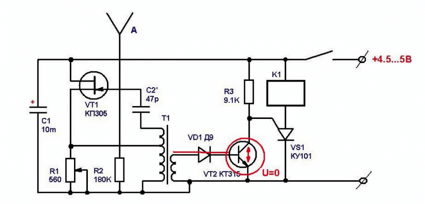
 An example of a simple light sensor circuit using an operational amplifier:
 Figure No. 2 - Simple light sensor, diagram
 It should be understood that as the network sensor itself, you use any photocell suitable for its parameters; the circuit is given as an example using a photodiode. The principle of operation of the circuit is very simple, the photo diode acts as a current source. When light falls on a photodiode, it produces a certain current in it (depending on the intensity of the radiation), the signal is amplified using any known and suitable amplifier circuit (in this case, an example of a circuit using an operational amplifier is given, the gain is set by selecting a resistor located in feedback). The output voltage is proportional to the incident light. Thus, the resulting signal at the output of the circuit can already control, for example, an electronic relay or transistor in switching mode. You should not take this diagram as a standard, I just gave it as an example of constructing a diagram for a light sensor device; this kind of solution is quite simple, understandable and common.
A motion sensor for turning on the light increases the comfort of your home. It allows you to reduce energy consumption. Such sensors are also used to create security zone. Depending on the principle of operation, such structures are divided into several types, each of which has its own characteristics.
general information
A motion sensor is a special device that, using sensitive elements, detects the presence of a person or animal and automatically turns on the light. It is installed mainly in corridors and on local areas. That is, in places with a relatively high flow of people.
Before answering the question of how to make a motion sensor, you need to decide existing types such devices. This equipment is classified according to its installation location. Sensors are:
- external;
- internal.
The first type of device has higher requirements for the quality and type of material from which its body is made. External sensors differ in their maximum coverage area. The latter term refers to a certain area of territory, the movement along which is capable of being “detected” by the sensor.
A homemade motion sensor does not have any type requirements lighting fixture. However, some specialized models must be connected to strictly defined floodlights.
According to the mechanism of operation, the motion sensor for turning on the light is:
- Infrared. Such devices respond to the temperature of an object falling within the sensor’s coverage area. Infrared sensors are mainly used indoors, as they are highly sensitive to environmental changes.
- Microwave. The sensor detects changes in radio frequencies. It is tuned to a specific range of signals. If an object appears in the “visibility” zone, the sensor registers its presence and transmits information to the alarm device. He turns on the light.
- Ultrasonic. It is considered the most simple device for lighting. These sensors feature a robust design.
At home, it is easier to make a motion sensor with your own hands using an ultrasonic or infrared sensor. The disadvantage of such a device is that it reacts to animals.

Conditions for installation
Before creating your own motion sensor, you need to decide on a number of important conditions. The latter affect the parameters of the future device. Such conditions include:
- Selecting an installation location. The design of the sensor depends on this parameter. In particular, if it is used outdoors, then it is necessary to make a moisture-resistant case for it. The installation location also determines the level of power the sensor must have.
- Presence of barriers. Chandeliers, trees and other objects interfere with the signal.
It is important to note that infrared sensors do not work if there is glass in their “visibility” area.
Making a sensor
Below we will look at the circuit of a simple motion sensor, which will consist of a transmitter, receiver and power supply for them.
power unit
Both the receiver and the transmitter are powered by a constant stabilized voltage of 12-16 V. Moreover, their total consumption does not exceed 50 mA.
Thus, any 12 V power supply can be used as a power supply, for example from an old router. Or you can collect your source using one of the many schemes on the Internet. Our consumption is minimal, so any will do.
Transmitter
The transmitter is assembled on the NE555 chip. The transmitting element is an IR diode LD274, the viewing angle of which is 10 degrees, which must be taken into account when installing the transmitter.

Receiver
A BPW40 phototransistor is used here as a sensitive element, and a BS-115C relay is used as an actuator. The phototransistor has a viewing angle of 20 degrees, which should also be taken into account when installing the receiver. Taking into account the sensitivity of the photoreceiving element, the distance from the transmitter to the receiver will be about 5 meters, which is quite good.

Conclusion
IN assembled form our receiver and transmitter will look like this:


All that remains is to make sure that the receiver relay switches the light bulb, LED strip or sound alarm (at your discretion).
Light sensors are quite common today. They differ greatly in their design parameters. First of all, this is due to the fact that there are many photovoltaic cells on the market. However, there are many models with different types adapters. However, to understand this issue in more detail, you should study the structure of these devices. Only after this will it be possible to proceed directly to assembling the light sensor.
Classic device diagram
The most standard scheme The sensor for light includes a photocell. In this case, nonlinear adapters are often used. However, linear modifications are also in demand today. The circuit of a standard light sensor also contains capacitors of various capacities. They can be arranged in sequential or parallel order. The sockets are installed directly for the lamps different diameters. Board systems are most often of the multi-channel type.
Model with magnetic photocell
With a magnetic photocell, the light sensor (diagram shown below) is most suitable for indoor applications. However, the model can only be used outdoors at above-zero temperatures. In order to assemble a light sensor with your own hands, it is more advisable to use a 5 V lamp. In this case, the cartridge can be purchased separately for the device in the store. The next step is to directly install the photocell.
For these purposes, you need to use a plastic case. After installing the photocell, a cardiode conductor is installed to transmit the signal. The capacitance of this element should not exceed 3 pF. Otherwise, the incandescent lamp may not withstand the heavy load. Direct connection to the 220 V network is carried out in the first phase. To do this, only the upper contacts must be closed. The conductor in this case can be used with the marking PP20.

Application of broadband photocells
This type of light sensor is not easy to assemble. First of all, you need to find a good photocell. To install it you will need a durable case. Additionally, it should be noted that it must be sealed, since the above photocell does not tolerate high humidity. It is also not recommended to use it at sub-zero temperatures. However, in enclosed spaces it can serve good service. Integral capacitors are most often used for it. They differ in capacity. In this case, much depends on the selected incandescent lamp.

If we consider the 5 V option, then capacitors in this situation can be used at 15 pF. In this case, the light sensor must be connected to the network via an adapter. Control boards are often used to regulate the power of the device. Today, multi-channel models are in great demand. In order to connect the light sensor to a 220 V network, you cannot do without an auxiliary adapter.
Dipole resistor sensor
Dipole resistor light sensors for lighting are widely used. Photocells in models are installed mainly of the spectral type. This option is ideal for the street. It can be used effectively even at temperatures of -20 degrees. In this case, the resistors will not short-circuit. In this case, only one capacitor will be required for installation. It must be selected open or closed type. However, the capacitor capacitance should not exceed 5 pF.

Amplifiers in such a device are used quite rarely. It is much better to install regular controllers for control. Contact systems for connection are single-phase. However, in this situation, it is necessary to first look at the switchboard. Only after this will it be possible to decide on an adapter so that the light bulb does not burn out.
Wave capacitor sensor
This type of light sensor can be assembled by preparing a magnetic photocell. Diode resistors are most suitable for the model, and their capacity must be at least 30 pF. Sensors of this type differ significantly in sensitivity. The amplifiers are installed at medium power. Modulators for the device are more suitable for the integral type. In this case, the sensitivity parameter will be at the level of 22 microns. It should also be noted that the diffuser in this case can be connected directly through the power supply.
Using Selective Capacitors
This type of light sensor is highly sensitive. These devices are not suitable for the street. However, much depends on the type of photocell. If we consider integral modifications, then they high humidity not to be afraid of. They are also insensitive to sub-zero temperature, and the device can be used in cold weather. Resistors are most often installed in the open type.

At the same time, a wide variety of management boards are suitable. In order to assemble the model yourself, it is more advisable to select adapters with auxiliary adapters. The light sensor is connected through the first phase. In this case, the contacts must be secured primarily from above. In order to check the grounding, you need to use a tester.
Ultra-sensitive light sensors
An ultra-sensitive light sensor is suitable for enclosed spaces. Most often, models are installed in office buildings. Thus, you can save quite a lot on electricity. In order to independently assemble an ultra-sensitive modification, it is better to purchase a magnetic type photocell. It is more advisable to select resistors with a high conductivity parameter.

In this case, you can use the simplest adapter. In this case, amplifiers, as a rule, are not used. An auxiliary adapter is required to connect the sensor. As a rule, it is used for two contacts. To ensure that system failures occur as rarely as possible, many experts recommend using resistance modules. You can usually find them in the store marked 10 ohms.
Modifications with reduced sensitivity
This type of light sensor is specially designed for use in harsh environments. weather conditions. On average, models can withstand temperatures down to -20 degrees. They install exclusively integral photocells. They differ in that they are practically not afraid of high humidity. At the same time, they can withstand minor mechanical damage.
The same cannot be said about magnetic analogues. In order to independently assemble a light sensor (outdoor), you will need a high-capacity capacitor. Additionally, low-power resistors are used for stable operation. You can install a wide variety of controllers for the sensor.

Modifications with membrane amplifier
Assembling a sensor with a membrane amplifier can be quite simple. If we consider the most simple modification, then it is more advisable to select a 5 V lamp. In this case, the cartridge diameter should be 4.5 cm. After fixing the photocell, it is necessary to fix the resistor. If we consider a model without a control board, then the amplifier should be installed near the output switch. In this case, the connection must be made through an adapter with insulation.
If we consider a model with a control board, then first of all it is important to solder an auxiliary adapter to the photocell using a blowtorch. Only after this is the switch with contacts connected to the system. In this case, the conductors need to be brought to the side and insulated to prevent short circuits.
Home use automated systems allows significant energy savings. For example, by installing a sensor on the street lighting on the approach to the house, in the entrance, hallway, or pantry, you will save yourself from the need to fumble for the switch in the dark and will never forget to turn it off. In this article we will talk about the features of sensors and how to make a motion sensor with your own hands.
Briefly about sensors
The motion sensor switches the load in the presence of external influence, which depends on the type of sensor and its operating principle. When the presence or movement of a body is detected, power is supplied to the load through a triac or electromagnetic relay. Anything can act as a load: a light bulb, a heater, a loudspeaker, as long as the load power does not exceed the maximum switching power of the sensor. Usually maximum power load about 1 kW.
If you need to turn on more power, you need to add another relay to the circuit so that the power terminals of the motion sensor turn on the voltage to the relay coil.
How the device works
The operating principle of the sensor depends on the type of connection diagram and the element used. Although their task is the same, their methods of implementation various sensors movements can be divided into groups according to the principle of their action. Let's look at the advantages and disadvantages of each of them.
Contact or magnetic
The simplest option is to use a mechanical limit switch; with it you can turn on the light when the door is open or closed, for example. This is not exactly a sensor, but still, the simplest way to implement automatic switching on of devices.
The next option is a reed switch (sealed contact), its essence is as follows: in a glass flask there is a pair of contacts that can close or open under the influence of magnetic field. In this case, it is installed on the door permanent magnet, and on doorway(platband) there is a reed switch. Its contacts are often not capable of passing large currents, so they can be used to turn on the relay winding to increase the switching capacity.
Motion sensor circuitIR sensor
Infrared motion sensors respond to infrared radiation, these are radiations with a wavelength of 1± mm or a frequency of 300-400 GHz. The PIR sensor is used as the main sensitive element. It records changes in the amount of radiation on it.
IR radiation is thermal radiation.
This means that in the IR range a person looks like a large source of radiation. In this case, the temperature of the sensor itself does not significantly change its operation. Information from outside world must hit the sensor, for this radiation is collected by a group of lenses, such as a Fresnel lens. Outwardly, it looks like a window in a casing with ribbed glass.
Depending on the design, the viewing angle of IR motion sensors can reach up to 360 degrees; in this case, several pyroelectric elements (PIR) are usually installed inside, and the lenses focus on them from the corresponding visibility zones. Such wide-angle sensors are needed to record movement from all sides, so as not to install several narrow-angle sensors; one is installed at 360 degrees on the ceiling.
 IR sensors react to heat
 Advantages:
- price;
- simplicity;
- prevalence;
- works well indoors;
- good adjustments;
- Does not irritate animals.
Flaws:
- unreliability;
- problems when working outside.
Since it reacts to heat, it has many “harmful” factors for precise operation. False alarms occur in response to any gust of warm wind or a switched-on heater, and the background temperature should differ (to a lesser extent) than the human temperature. Therefore, it is unlikely to work in the kitchen when you find yourself in front of a hot stove, but is it needed there?
Laser or photosensor
A laser sensor is a pair of elements, an emitter and a receiver, and the emitter can be in the IR spectrum so as to be undetectable by the human eye. Such sensors are used in alarms; when you cross a laser beam, it does not reach the photodetector (photoresistor or photodiode) and the circuit generates a signal about the presence in the room. How to use this signal depends on further connections; you can turn on the light through a time relay or siren or a signal to the security and safety system control unit.
Another type of photo sensors looks like this: the LED emitter and receiver are not installed opposite each other, but nearby, in the same plane, the radiation is reflected and hits the optical receiver, when you enter the field of view of the sensor, the motion sensor is triggered. Another name is obstacle sensor.
Advantages:
- Simplicity.
Flaws:
- Narrow field of view.
- Specificity of application.
 Specifics of the action of the motion photo sensor
 Microwave
Microwave motion sensor - works on the principle of a radio receiver-transmitter. High-frequency oscillations are generated in the circuit and received here; the receiving part is configured in this way: when no one is nearby, the relay is turned off. When you get into work area receiver - the oscillation frequency changes, as a result of which a signal is sent from the detector diode that it is necessary to turn on the power element and apply voltage to the load.
Flaws:
- High-frequency radiation is harmful to health (although you carry a smartphone in your pocket, there is even more radiation there).
- Relatively high cost.
- False alarms are possible due to impacts outside the observed area.
Advantages:
- sensitivity allows you to detect an object behind a door or glass, for example;
- detects even the slightest movements.
 This is how a microwave motion sensor works
 Ultrasonic
Another type is built on the “emitter-receiver” principle – an ultrasonic motion sensor. The frequency of the ultrasonic wave lies in the range above 20 kHz but below 60 kHz. The detection principle is based on the Doppler effect. The length of the reflected wave changes, the receiver records this change and gives a signal about the presence and movement of a new object.
Flaws:
- Animals may react to it. Dog repellers use ultrasonic emitters.
- If you move slowly, the ultrasonic DD may not work.
Advantages:
- reasonable cost;
- insensitive to changes in environmental conditions.
Circuits for homemade motion sensors
We propose to consider several schemes suitable for repeating and studying the principles of operation of sensors. In addition, the microwave will also help you master the basics of radio transmission technology and signal detection, and circuits using microcontrollers will make it possible to create a modular version with ready-made solutions for Arduino.
 Presence detector circuit
 Capacitive
Let's take the normal state to be when there is no one near the sensor, and the triggering state to be when you are nearby.
Transistor VT1 is a generator unit on a field switch configured at 100 kHz. The oscillatory circuit L2C2 is tuned into resonance with it. Electrically connected to the generator through R2. VD1 (detector diode). The frequencies are indicated in the absence of external influences, i.e. you do not touch the circuit and are removed from it. Part DA1 is a comparator, needed to compare the signal from the diode and the reference voltage specified through R3. In a normal state, the output should tend to zero. In this case, the signal at the non-inverting input of the comparator “–” is 5 V, and at the output – 0 V.
When you approach the sensor, the capacitance will increase, the frequency of the generator will decrease, you influence the frequency of the generator, and L2C2 the frequency is set by an oscillating circuit in parallel with capacitance and inductance.
The resonance between the oscillator and this circuit disappears, and the voltage at the non-inverting input drops. Since the voltage at the inverter increases, the output begins to pull up to the supply voltage and stops at 8 volts (approximately), they can be used to control relays, through a transistor to amplify the output current, thyristors and other devices from which you are already powering the load.
Both coils are wound on ferrite rings 2000 NM, 20 mm with an outer diameter of 100 turns of PEV-2 wire 0.2 mm, turn to turn. In turn, L1 has a tap from the 20th turn, and L2 from the 50th turn (from the middle). Wind it so that the distance between the beginning and the end is no less than 0.3 mm.
Sensor – 2 pieces of wire 1 mm in diameter and 1–1.5 m long are located at a distance of 20 cm from each other.
Setting: we measure the voltage of C5 with a voltmeter, rotating the tuning C4, we achieve the maximum voltage (2.5–5 V), if the voltage is lower, we add a 15 pF constant capacitor in parallel with C3, if there is still not enough voltage, we reduce R1, but not less than 500 kOhm. The next step is to unscrew R3 to the bottom position according to the scheme, and R2 to the middle position. The LED connected to the op-amp output through a resistor lights up. Rotate R3 to make it go out. Carry out the settings directly where it will be installed. If you carry out the setup on the desktop, and then place the sensor where you planned, you will most likely have to configure it again.
Thermal sensor on Arduino
To build a PIR motion sensor project on Arduino you need:
- PIR sensor HC-SR501.
- Arduino UNO (or any other similar one).
- Power supply 4–6 V.
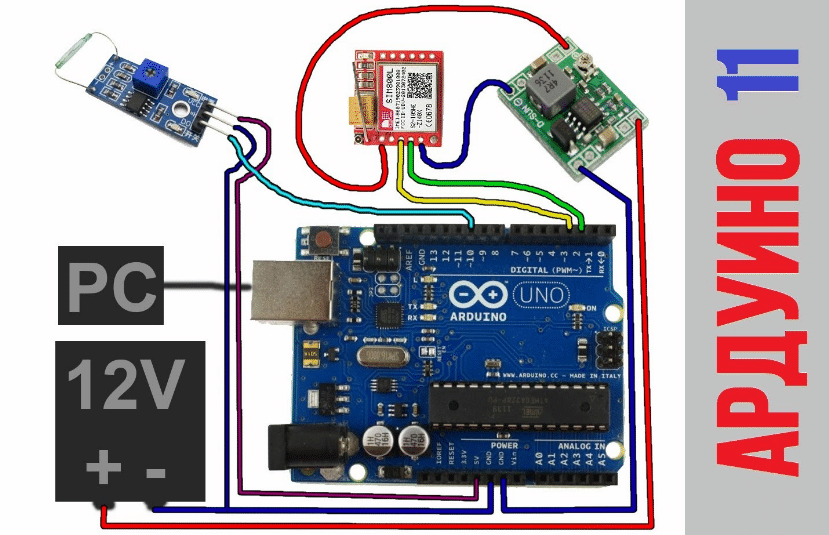 Connecting sensor elements
 HC-SR501 – contains 1 pyroelectric element, it is covered with a lens, and the necessary harness on printed circuit board. Trimmer resistors are located on one side of the board to adjust sensitivity and delay time. The output signal has an amplitude of 3.3 volts, and the supply voltage is 5–12 volts. The maximum distance at which the sensor will operate is 7 m, and the time delay after activation is up to 5 minutes.
 Sensor connection diagram
 Connection diagram for controlling light via a relay.
 Light control
 Visual diagram of connections on a solderless breadboard