A ship's power plant is a set of mechanisms installed on a ship that serve to convert thermal energy into mechanical energy when burning fuel and for ship movement, cargo operations and other ship needs, for rotating propulsors, propellers, and paddle wheels. The SSU consists of main engines and auxiliary mechanisms: pumps, compressors, generators, etc. A vessel with an internal combustion engine is called a motor ship. The auxiliary engine provides electricity generation.
Classification of ship propulsion systems: By location (outboard, stationary), By engine type (piston, gas turbine, steam piston, steam turbine, thermonuclear) Propulsion - a device for converting the energy of an engine or a natural energy source into energy that sets the ship in motion. Classification of propulsion: oar; sailing; wheeled; screw; water jet; reactive.
8. Ship devices. Purpose of ship devices.
Steering, anchor, mooring, towing, coupling, boat, cargo devices.
Steering gear consists of: steering wheel, stock, steering gear, steering mechanism.@
The rudder consists of a feather and a stock rigidly attached to it. The feather consists of one or several streamlined plates. Based on the cross-sectional shape, a distinction is made between flat (small self-propelled and non-self-propelled vessels) and streamlined rudders.
Types of rudders: balancer@-axis of the stock passes in the area of the center of hydrodynamic pressure, i.e. the stock is installed at some distance from the nose edge of the rudder. The semi-balanced@-axis of the stock passes between the leading edge and the center of hydrodynamic pressure.
Steering gear: manual - used on small ships as the main one and installed in the wheelhouse; electric - installed in the tiller compartment; electrohydraulic - small, smooth and quiet in operation; steam.
The steering drive transmits forces from the steering machine to the arm stock. It includes: a sector, cable rods. The sector is called a tiller.
Lifeboat device serves to communicate the ship with the shore, as well as to rescue the crew in emergency situations. It consists of a boat, davits with winches, davits, rostrum blocks and stowage fastening devices for the boat.
Work and rescue boats.
Keel blocks are devices for storing a boat on deck.
Davits are a device for raising and lowering a boat. The davit block design allows you to raise and lower boats with people and equipment.
Loading device designed for loading and unloading operations when onshore crane equipment is not available. The cargo equipment includes ship slewing cranes, cargo booms and bilge lifts of various designs.
Load capacity 300-600t.
Signaling means: sound (horn), siren, smoke bombs, etc.
9. Ship systems. Purpose of ship systems.
Each ship system consists of:
Pipeline network for moving the corresponding medium through them
Compensators in long pipelines
Fittings for regulating the movement of the medium
Mechanisms: pumps, fans, compressors, devices for changing the state of the transported medium
Various types of sensors
Tanks, cylinders, tanks for storing liquids and gases.
According to the control principle, ship systems are divided into:
Centralized - the system is served by 1 or a group of pumps located in the engine room;
Autonomous - the mechanism serves only 1 of the ship’s compartments;
Group-mechanism serves a group of compartments;
Decentralized - all consumers are served by one pump through a common main pipeline.
According to the purpose and nature of the functions performed, ship systems are divided into groups: bilge, sanitary, fire, artificial microclimate, special tanker systems.
Bilge system. This includes:
Ballast. Serves for receiving or pumping water from ballast compartments in order to change the trim of the vessel. Used during empty runs. The amount of water ballast can reach 20-40% of the vessel’s carrying capacity.
Trim or roll system. It is mainly equipped with icebreakers; for rocking the ship by pumping ballast from the tanks on the 1st side to the tanks on the opposite side or from the bow to the stern compartments and back.
Drainage. Serves to remove water accumulating under the hull of the engine room and holds. The water must be removed into special containers located in the hull of the vessel
Drainage. Served for pumping large masses water when there is a hole. Rescue ships are usually equipped with such a system.
Sanitary system.
Water supply system - preparation and supply of drinking and sea water to places of consumption; consists of tanks for storing supplies drinking water, piping systems supplying water to cabins and service areas, as well as pumps and pressure-maintaining devices.
Wastewater is used to collect and dispose of sewage and sewage water.
Scuppers - removing water from the deck during cleaning or rain.
Fire protection system.
Fire alarm - detection of the source of fire. On ships the following systems are used: water extinguishing; steam extinguishing; foam extinguishing - chemical or air-mechanical foam; carbon dioxide extinguishing system - to prevent fires on oil tankers, it uses a system for filling compartments with inert gases.
Artificial microclimate system.
Heating, ventilation, air conditioning, refrigeration and special systems. The heating system should ensure the air temperature in the room is 18-20 degrees.
Special tanker systems.
Oil tankers provide:
cargo. Allows you to unload oil products on your own.
stripping refers to cargo, but has lower productivity.
heating serves to heat the cargo for cargo operations.
gas outlet - removal of petroleum product vapors from cargo tanks into the atmosphere.
The cargo tank washing system is used to remove residual oil products adhering to the frame and lining inside the tanks.
10.Radio navigation equipment. Types of premises on the ship.
Radio navigation equipment can be divided by function:
Informing about external conditions: wind indicators, echo sounders, logs
Information about the position of the ship in relation to land and the position of other ships in relation to the ship: radars, thermal imagers, GPS navigators, chart plotters
Communication means that allow you to receive and transmit information, both manually and automatically: walkie-talkies, weather stations, rescue beacons.
Autopilots.
The main means of external communication is radio communication. Radio exchange is carried out in telephony, digital selective calling, and letterpress modes. The satellite communications system provides seafarers with a direct dial telephone, telex, fax, e-mail, and data transfer mode. Special communication systems ensure the transfer of information to ships to ensure navigation safety
Since 1999, all ships have been equipped with Global Maritime Distress and Safety System (GMDSS) radio equipment. The main purpose of the GMDSS is the operational organization of the search and rescue operation of an emergency vessel by the coastal rescue coordination center (RCC) with the involvement of ships and other means located in the disaster area.
Ship premises are formed by dividing the ship's hull into compartments and dividing compartments, superstructures and deckhouses with decks, platforms and enclosures into separate enclosed spaces. The number and location of ship premises, their equipment and dimensions are determined by many factors. According to the Rules, ship premises are divided into control stations, residential, service, cargo, machinery spaces, fuel and lubricating oil storage facilities, pump rooms, production premises, and special category premises. Control stations. The ship's control station is located on the navigation bridge in a closed room in the wheelhouse, which has two exits - one on each wing of the navigation bridge - and a passage from side to side.
Ship systems are complexes of pipelines, pumps, containers (for example, tanks, cylinders), shut-off and switching valves, instrumentation, etc., designed to move and store liquids or gases in order to ensure production activities, create habitable conditions, and combat for the survivability of the vessel. Number ship systems may vary and depends on the size of the vessel, its type and purpose.
Drying system. The purpose of this system is to remove moisture accumulated there from the lower part of the body and from the bilges through leaks various connections(flanges, deadwood, etc.), as a result of sweating, water spills during cleaning and for other reasons. The influx of sea water can be caused by leaks in the ship's hull, so monitoring the water level in the bilges is an important responsibility of the watch service.
In case of emergency water leakage (holes, cracks in the hull plating), more powerful drainage means are activated. There is also a system for transferring water from rooms or compartments where there are no drainage or drainage facilities to other rooms where such facilities are available.
Ballast system. This system is designed to receive, pump or pump sea water in order to change the list or trim of the vessel, to improve its stability, and change draft. It includes ballast tanks (tanks, compartments), pipelines, pumps, etc., which in a number of designs perform the same functions in a drainage or drainage system. Ballast tanks are usually filled completely (pressed in), since a partially filled tank negatively affects the stability of the vessel due to the transfer of liquid from side to side.
Fire protection system. The purpose of creating a fire-fighting system is to warn of fire, smoke or a significant increase in temperature in the ship’s premises, as well as to supply fire-extinguishing agents to the source of the fire and prevent the spread of fire.
Fire alarms come in different types. Most often, it includes heat-sensitive sensors installed on the ceilings of rooms (cabins, corridors, etc.). They are electrically connected to a common display located in the ship's control room. There are other types of fire alarm devices (of the "break the glass and push the button" type) often used in coastal buildings.
A water fire system for extinguishing a fire with water consists of pipelines, fire horns, at which fire hoses with tips are placed, allowing you to create a strong jet or diffuse irrigation. In rooms intended for storing flammable substances, water irrigation may be provided, which is turned on automatically when the temperature rises, while simultaneously sending an alarm signal to the ship's control posts. In some places, devices are installed to create water curtains that prevent the spread of fire or cool any structures during a fire.
There are also steam extinguishing systems, with the help of which a burning room can be filled with steam, which prevents the flow of air to the fire.
Burning petroleum products are extinguished using a foam extinguishing system that supplies a foam-forming liquid with compressed air or a liquid that forms fire-extinguishing foam as a result of a chemical reaction.
To extinguish a fire, a carbon dioxide extinguishing system can also be used: the burning room is filled with carbon dioxide (less commonly, inert gas) from cylinders, where it is stored under high pressure.
Steam extinguishing and carbon dioxide extinguishing are used in rooms that can be sealed after evacuating people. These systems, as a rule, have remote control (usually mechanical) from posts located on the upper deck.
Portable fire extinguishers (foam and carbon dioxide) of conventional types are placed on board in numerous visible and accessible places.
Ventilation and air conditioning systems. Ventilation of ship premises is equipped for the following purposes: creating comfortable conditions in terms of temperature, humidity and air composition in living and other premises; removal of harmful products (smoke, gas, etc.) from industrial premises, for example, machine and boiler rooms, workshops; creation optimal conditions storage of cargo, supply materials (for example, ventilation of holds).
Ventilation can be natural or artificial. Natural ventilation is ensured by wind and temperature differences through ventilation fungi and funnels, open portholes, doors, etc.
Artificial ventilation (injection and exhaust) is provided through a system of ventilation air ducts using blowers driven by electric motors. Mechanical ventilation on ships sailing in tropical areas can be combined with an air conditioning system that maintains the desired temperature and humidity regardless of external conditions.
Sanitary systems. Heating on ships can be water, electric (electric heating pads), air (supply of heated air through a blower). artificial ventilation) or steam (no longer used on modern ships).
The domestic water supply system provides water for various needs. Drinking water is supplied to the galley, drinking fountains, carbonation units, etc. It is stored in special tanks, its quality is subject to sanitary control, and bactericidal measures are carried out.
Washing water is supplied to washbasins, showers, baths, bathhouses, etc., both cold and heated, through separate pipelines.
Seawater for sanitary purposes is supplied to the latrines, for tidying on the upper deck, and can also be supplied to the showers.
Where necessary to ensure high costs fresh water Desalination devices may be installed on ships.
The drainage system is equipped to collect and subsequently remove contaminated and fecal water from the vessel.
Special ship systems for production and technological purposes. Depending on the type and purpose of the vessel, this type of system may also include fuel and refrigeration systems, production systems of fresh and sea water and sewerage, a fish oil system, etc.
The fuel system is designed for receiving, storing, supplying supply tanks, moving (pumping) liquid fuel from one tank to another, as well as for transferring it to other vessels.
The refrigeration system is used to ensure low temperatures in holds where fish or other perishable products are stored, to freeze seafood, produce ice, and also to cool food pantries that store provisions for the ship's crew.
Pipelines and fittings of ship systems have assigned markings (colored stripes, inscriptions), violation of which, for example, during painting work, is unacceptable. Any noticed malfunction of the ship's systems should be immediately reported to the watch commander. Oil spills that lead to sea pollution are especially unacceptable.
International convention on the Prevention of Pollution from Ships of 1973 provides for very strict sanctions against persons guilty of pollution of the sea and especially with petroleum products. Thus, in the Mediterranean, Baltic, Red Seas and the Persian Gulf, the discharge of oil from ships is completely prohibited.
The discharge of sewage from vessels is prohibited within 4 miles of shore. Within 4-12 miles, waste must be previously disinfected and finely ground, and all types of plastics (plastics) are not allowed to be dumped into the sea.
Questions for self-control
1. Name the types of steering wheels and their main differences.
3. Name the main elements of the anchor device.
4. Name the main types of ship anchors.
5. List the elements of the mooring device.
6. Draw a diagram of cargo booms that work “on the telephone” and explain its operation.
7. Name the brands lifeboats, approximate dimensions and weight.
8. What is included in the supply of lifeboats?
9. Briefly describe the structure of an inflatable life raft (ILS).
10. What applies to personal life-saving equipment?
11. What are the standards for supplying a ship with life-saving equipment?
12. Name the ship systems and indicate their purpose.
The operation of ship systems ensures the survivability of the vessel, i.e. navigation safety, the necessary conditions habitability, safety of cargo, as well as the performance of special functions related to the purpose of the vessel, for example on tankers, rescue ships, fishing vessels.
Share your work on social networks
If this work does not suit you, at the bottom of the page there is a list of similar works. You can also use the search button
MINISTRY OF EDUCATION AND SCIENCE OF UKRAINE
NATIONAL UNIVERSITY
"NIKOLAEVSK UNIVERSITY OF SHIPBUILDING NAMED AFTER ADMIRAL MAKAROV"
Department of Shipbuilding
ABSTRACT
from discipline
Ship system
on the topic: “Ship fire protection system”
Student _ V _ course _ 5 11 2 group
Chernyaev Maxim Igorovich
(nickname and initials)
Kerivnyk
Doctor of Technical Sciences Professor_Zaitsev V.V.___
(posada, old title, scientific level, nickname and initials)
Kherson - 2014
Introduction…………………………………………………………………………………3
1 General concepts modern fire protection systems………………..4
2 Types of fire protection systems……………………………………………………......6
2.1 Water fire extinguishing system………………………………………………………..6
2.2 Fire extinguishing sprinkler system……………………………..8
2.3 Deluge fire extinguishing system…………………………..……...10
2.4 Foam fire extinguishing system……………………………...........11
2.5 Powder fire extinguishing system………………………………..12
2.6 CO2 fire extinguishing system ………………………………………..13
2.7 Aerosol fire extinguishing system…………………………….14
Conclusion…………………………………………...………………………..16
List of used literature………………...………………………17.
INTRODUCTION
Ship systems this is a complex of pipelines with fittings and mechanisms serving them,tanks, apparatus, instruments and means of control and monitoring of them.
Ship systems are a set of specialized pipelines with mechanisms, apparatus, instruments and devices.
They are designed to move liquids, air or gases in order to ensure the normal operation of a ship (with the exception of a power plant, the pipelines of which are not included in the ship systems).
The operation of ship systems ensures the survivability of the vessel, i.e. navigation safety, necessary living conditions, cargo safety, as well as the performance of special functions related to the purpose of the vessel, for example on tankers, rescue ships, fishing vessels. Civil vessels usually provide:
- Bilge systems drainage, drainage, bypass, oil-containing bilge water.
- Ballast systemsballast, trim, heeling, replacement.
- Fire extinguishing systemswater fire extinguishing, water irrigation, sprinkler, water spray, water curtains, steam extinguishing, foam extinguishing, carbon dioxide extinguishing, volumetric chemical, inert gases, powder fire extinguishing.
- Domestic water systemsfresh domestic water, drinking water, washing water, domestic sea water, domestic hot water.
- Waste systems waste water, domestic water, open deck scuppers.
- Microclimate systemsventilation, air conditioning, heating (steam, water, air).
- Systems refrigeration units refrigeration.
- Household steam supply systems.
- Compressed air systems.
- Marine equipment cooling systems.
- Hydraulic system.
Auxiliarymeasuring, air, overflow, communication, alarm, control systems.
Special systems:
Tanker cargo, stripping, gas exhaust, washing of cargo tanks, irrigation.
Rescuers soil erosion, soil suction, drainage and rescue, compressed gases.
Commercial fish oil, brine, fish feed.
1 General concepts of modern fire protection systems
Modern systems Fire protection is based on the use of the latest means and methods of detecting and extinguishing fires and reducing losses from the use of fire extinguishing agents. These include, first of all, the use of finely sprayed water and aerosol spray water, high expansion foam. All stationary installations of the listed types are designed to extinguish fires in confined spaces.
In modern fire extinguishing installations of the sprinkler deluge type, the use of sprinklers, for example, “Aquamaster” and similar ones, makes it possible to obtain droplets of water supplied for extinguishing with an average diameter of 100150 microns. Recently, not only sprinklers installed vertically, but also with horizontal installation have appeared on the market. The water pressure in such installations at the outlet of the sprinkler should be within 0.51.2 MPa (512 kg/m2). The use of finely sprayed water makes it possible to reduce the amount of water supplied for extinguishing by 1.52 times and increase the efficiency of its use.
The use of aerosol spray water (superheated water) allows extinguishing with an average droplet diameter of about 70 microns and eliminating the flaming combustion of almost all combustible materials that do not react with water to release large quantity heat and flammable gases. The time to extinguish the flame of solid flammable materials and liquids, as a rule, does not exceed one minute. The use of installations of this type is limited by the fact that to obtain aerosol spray water it is necessary either to have a container in which the water is constantly located at a temperature of 150-170 ° C, or special equipment that allows the water to be heated to the required temperature in a short time.
Currently, high-expansion foam (foam expansion 400 or more) is becoming increasingly widespread to protect closed spaces. The use of fire extinguishing installations with high expansion foam allows you to fill the protected volume with foam in a short time and eliminate the fire. To obtain high-expansion foam, you should use only those foaming agents for which the certificate indicates that they allow you to obtain high-expansion foam. The use of such installations makes it possible to significantly reduce the amount of foam concentrate and water stored in the tanks of the foam fire extinguishing pumping station, and, consequently, the costs.
Remote controlled fire monitors and fire fighting robots are increasingly being used. Fire robots correspond in all respects to automatic fire extinguishing installations: they provide automatic fire alarm in the protected area, determine the coordinates of a fire and automatically extinguish the fire with sprayed water or low expansion foam. The area protected by one fire robot ranges from 5,000 to 15,000 m2 with a flow rate of water or foam solution from one barrel from 20 to 60 liters s”1.
The most widely used currently are fire monitors with remote control and scanning barrels. They are used for irrigation of load-bearing structures and trusses in machine rooms of power plants, in machine-building shops and other enterprises. Scanning barrels deliver jets of water according to a predetermined program, water supply mode (speed and trajectory of the barrel). Barrels of this type are the cheapest, and partly for this reason their use is much wider. The use of robotic monitors is partly constrained by reasons of their high cost and necessity constant maintenance which requires the involvement of highly qualified specialists.
The use of fire robots of other types and with the use of other types fire extinguishing agents so far negligible worldwide; Thus, their use is restrained for the same reasons as robotic trunks. But at the same time, it should be expected that the use of fire robots will increase quite soon with the advent of new types and designs, as well as a decrease in cost.
Oil and petroleum products are increasingly used to extinguish fires. modern means and methods using low expansion foam produced using fluorinated film-forming foaming agents. To extinguish fires of oil and petroleum products in tanks, the sublayer method of supplying low expansion foam has become quite widespread. However, it should be noted that this method is not applicable in all cases. This method should not be used to extinguish fires of flammable liquids with high viscosity, as well as polar liquids that destroy the supplied foam at a high speed. It is problematic to extinguish high-octane gasolines in which the content of polar liquids reaches 18-20%. To extinguish fires of polar liquids and mixed fuels, low expansion foam should be supplied from above using foam concentrates designed for this purpose.
To extinguish fires in tanks equipped with a pontoon, a combined method of supplying low expansion foam into the tank should be used. With this method, foam is applied to the surface of the flammable liquid and under the layer of flammable liquid at the same time. The use of this method of foam supply makes it possible to eliminate fire in almost all cases, including those when the pontoon is in the lower position, for example, when the tank is taken out of service for repair work.
2 Types of fire protection systems
Stationary fire extinguishing systems are installed during the construction of the ship. They are divided into linear and circular . Stationary installations allow you to quickly supply a fire extinguishing agent to a fire, bring it under control and ensure extinguishing.
2.1 Water fire extinguishing systemthe main system for protection, equipped regardless of the presence of other systems. The pipeline system consists of a main line with a pipe diameter of 100-150 mm and branches with a diameter of 38-64 mm. All sections of the water fire main running on open decks must have drain valves to drain the main in case of a dangerous drop in temperature.
Water fire extinguishing system (VPPS is intended for:
- providing high-pressure sea water to consumers of a complex of survivability control systems (LSS) - irrigation and water spray systems, watch and decampment protection systems;
- providing high-pressure sea water as working water for the ejectors of the hold drainage system;
- providing sea water to the “sea water” system intended for servicing the washing system during sanitation of l/s and servicing flushing in latrines.
VPPS is made according to ring pattern (see figure) with seven combat jumpers and consists of:
Figure 1 Diagram of a water fire protection system
- three turbopumps TPZHN-150/10 with a capacity of 150 cubic meters per hour and a head of 10 m.w.c., located in the bow engine-boiler room (MKO), the auxiliary boiler room (ABC) and the aft MKO and serving to supply sea water to combat jumpers No. 3, 4 and 5;
- four electric pumps NTsV-160/80 with a capacity of 160 cubic meters per hour and a pressure of 80 m.w.st., located in pairs in pump rooms No. 1 and 2 and serving to supply sea water to the service jumpers No. 1, 2, 6 and 7;
- seven combat jumpers, each of which is connected to one fire pump. Water is withdrawn to the consumers indicated above ONLY from jumpers;
- eighteen main isolation valves with remote control from the energy and survivability station (PEZh) using an electric drive, which serve to isolate the VPPS in combat mode and switch sections of the VPPS to supply water to other jumpers in the event of failure of any pumps or sections of the system. These valves are marked on the diagram exclamation mark;
- remote monitoring and control system, consisting of local control pressure gauges located at the pumps, remote pressure gauges located on the mnemonic diagram in the PEZH and the spare PEZH (PDU KMKO), as well as pressure sensors connected to each jumper and serving to automatically start the duty electric fire pump when pressure drop in the VPPS to 6 kgf/sq.cm in everyday mode. In addition, the remote monitoring and control system includes ballast control equipment for electric fire pumps.
VPPS operates in two modes:
- combat mode - in this mode, all main isolation valves are CLOSED and ALL seven pumps are operating. At the same time, autonomous power supply of jumpers with their consumers is ensured. If the pump serving the jumper fails and any side branch of the “ring” is in good condition, by switching the corresponding valves, the non-working jumper is connected to the working ones.
- daily routine- in this mode, TPZHN No. 2 operates when parked, while TPZHN No. 1 and 3 operate while on the move. All electric pumps that are not undergoing scheduled preventive inspection or repair (PPO and PPR) are on duty - ready for automatic start when the pressure in the VPPS drops up to 6 kgf/sq.cm.
The normal pressure value in the VPPS is 7-8 kgf/sq.cm.
In general, this design of the VPPS is considered classic and the most reliable, even in comparison with the design of a similar system on ships of later projects. Most strengths such a decision are:
- very short combat jumpers located across the ship's hull (minimizing the amount of potential critical damage);
- the presence of three turbo-fire pumps. Based on the concept of ensuring the operability of the steam power plant (SPS) in the absence of electricity on the ship (full self-sufficiency), the supply of water to the HPPS will also occur despite the lack of electricity.
The weak point of the design solution is the low location of the combat jumpers and side branches of the “ring”, i.e. the combat jumpers, together with the outlets to consumers, fall into the affected volume during underwater explosions. If the jumpers were located near or at the level of the unsinkable deck (lower deck), this drawback could be eliminated.
2.2 Fire sprinkler systemsused on ferries and passenger ships to protect residential premises, adjacent corridors and public spaces. Their purpose is to limit the spread of fire and reduce the temperature in the protected premises, which makes it possible to organize a reliable evacuation of passengers and crew members.
In all protected premises, a sufficient number of sprinklers and special valves with fusible inserts are installed to ensure the closed position of the valves. When the temperature in the premises rises, the fusible insert melts, the sprinkler valve opens, and water begins to spray throughout the room. On ships, sprinklers are usually used that operate at a temperature of 60-75 ° C;
Designations: 1 - Distribution pipeline; 2- Universal pressure alarm; 3-Control and control panel; 4- Pneumatic tank or impulse device; 5- Control and launch unit; 6 Normal valve; 7 Electric motor; 8 Pump; 9 Fire alarm station; 10 Compressor.
Figure 2 Diagram of a water fire extinguishing sprinkler installation
2.3 Deluge fire extinguishing systemthe layout of lines and installation of spray heads is similar to that of a sprinkler. Pipelines are not normally filled with water. When the system is turned on, the pump starts and supplies sea water to the main line to all sprayers finely sprayed water covers the protected area. Deluge fire extinguishing installations
used for irrigation of the cargo deck of horizontal loading ships and tankers, pipelines and open surfaces of gas carrier tanks. If a fire occurs, the deluge unit cools the metal decks and other ship structures, preventing the fire from spreading.Deluge installations are designed for simultaneous fire extinguishing throughout the entire protected area, creating water curtains, as well as irrigation of building structures, oil tanks and process equipment.
The deluge installation may consist of one or several sections. Each of them is serviced by an independent control and starting unit. Automatic activation of deluge units can be provided by one of the following incentive systems:
- in the presence of a group action valve a hydraulic or pneumatic system with sprinklers, a fire alarm system and an incentive pipeline, a cable system with fusible locks;
- in the presence of gate valves and electric drives fire alarm system with electric fire detectors.
2.4 Foam fire extinguishing systemused for fires in machinery spaces and pump rooms. All tankers are equipped with deck foam fire extinguishing systems.
Installation of air-mechanical foam on ships is recommended.
Legend: 1 Automatic water feeder (Pneumotank); 2- Pipeline from the main water supply; 3-Container with foaming agent; 4- Distribution water supply; 5- Shut-off and control device; 6 Foam sprinkler; 7 Signaling device; 8 Control and launch unit.

Figure 3 Diagram of a foam fire sprinkler installation
2.5 Powder fire extinguishing systemsAll ships transporting liquefied gases in bulk must be equipped. A ship may have several installations mounted on skids so that the areas they protect overlap each other.
Foam as a fire extinguishing agent has a high insulating and partially cooling property. When the installation is put into operation, water and foaming agent begin to flow into the mixer. The foam solution formed in the mixer flows to the source of the fire. At the exit of the foam solution, air ejectors are installed, in which the pricing process is completed due to air leaks.
The operating time of the installation depends on the supply of foaming agent in the tank. When all the foaming agent has been used up and water begins to flow through the outlets, the unit is turned off to avoid foam destruction. An important condition for extinguishing a fire is the maximum supply of foam during the first 3 minutes. Stationary fire foam extinguishing nozzles are positioned as follows:
so that any point of the protected premises is no more than 9 m away.
Based on the control method, powder fire extinguishing installations are divided into:
- Automatic installations fire detection is carried out by installing an automatic fire alarm followed by a signal to start the automatic fire alarm system.
- Installations with manual start (local, remote) the signal to start the AUPPT is carried out manually from the premises of the fire post, fire extinguishing station, protected premises.
Autonomous installations fire detection and powder dispensing functions are carried out independently of external power and control sources (as a rule, fire extinguishing modules are equipped with this function to increase the reliability of operation in the event of failure of external systems).
Legend: 1 Fire extinguisher housing; 2- Pneumatic valve; 3-Cylinder with compressed gas; 4-Guide pipe with weight; 5-Cable; 6 Manual start handle; 7 Easy lock; 8 Nozzles.

Figure 3 Diagram of an automatic powder fire extinguisher.
2.6 CO2 fire extinguishing systemused to protect cargo, machinery and pump rooms, storerooms, galleys. Stationary CO2 fire extinguishing installations are installed in machine and
cargo spaces of the ship. A CO2 fire extinguishing installation for machinery spaces is put into operation if previously taken measures did not allow the fire to be localized. Along the highway carbon dioxide is supplied in the liquid phase under pressure, expands at the outlet and dense gas is supplied to the fire zone, effectively displacing oxygen and reducing its content in the air to 15% or lower. Carbon dioxide as a fire extinguishing agent is neutral and does not damage expensive cargo and machinery.
Before the CO2 fire extinguishing installation is put into operation, the protected room must be sealed, 20 seconds before the gas is supplied, an automatic alarm signal is activated, at the same time a light board lights up, warning people of the danger. When an alarm sounds, all people must leave the premises. The chief engineer must ensure that people are evacuated from the machinery space. Without breathing apparatus, it is dangerous to enter a room where carbon dioxide has been supplied, even for a short time.
2.7 Aerosol fire extinguishing systemsdesigned to extinguish indoor fires associated with the use of flammable liquids, in the holds of ships, art galleries, museums, archives, cable tunnels, in various electrical installations under voltage, as well as in all cases where the properties of the substances and materials involved in combustion are not allow the use of water or air-mechanical foam for fire extinguishing, or when the use of installations gas fire extinguishing gives greater economic effect. Gas fire extinguishing installations are divided: according to the extinguishing method, according to the start-up method and according to the method of storing the fire extinguishing agent.
Based on the extinguishing method, these installations are divided into volumetric and local fire extinguishing installations. The volumetric extinguishing method is based on the uniform distribution of the fire extinguishing agent and the creation of a fire extinguishing concentration throughout the entire volume of the room, which ensures effective extinguishing at any point in the room, including hard-to-reach areas. Volume extinguishing installations are used in enclosed spaces where rapid fire development is possible. Local (local) extinguishing installations are used to extinguish fires of units and equipment when it is impossible or impractical to extinguish in the entire room. The principle of local fire extinguishing is to create a fire extinguishing concentration in a dangerous spatial area of the room. Local extinguishing can be carried out either using automatic installations or manual means.
According to the method of starting up gas fire extinguishing installations, there are:
- with cable (mechanical);
- pneumatic;
- electric;
- combined start.
Based on the method of storing the fire extinguishing agent in cylinders, installations are divided into installations:
- under pressure;
- no pressure.
Designations: 1- Automatic start disabling unit; 2-Incentive pipe; 3-Incentive balloons; 4-Distributor valve; 5-Pressure alarm; 6 Outlet nozzles; 7 Incentive system attachments (sprinklers); 8 Manual valve; 9 Stop valve ; 10 Sectional fuse; 11-Launchers air cylinders; 12-Cylinders with fire extinguishing agent.
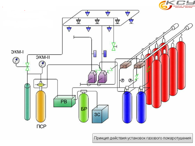
Figure 5 Scheme gas system fire extinguishing
Conclusion
IN last years reconstruction is carried out at a high pace in Ukraine, major renovation and technical re-equipment of industrial and public buildings for various purposes. This also applies to objects water transport. In large, medium-sized and even small cities where there are bodies of water (river, sea, lake), ships are used to furnish hotels, restaurants, and office premises. For these purposes, they use docked, passenger, permanently or temporarily operated vessels at the berth (shore), and also decommissioned vessels.
Fire safety on shipsis extremely important. The ships are autonomous, their premises with varying degrees of fire danger are located nearby, their structures contain flammable materials, there are ignition sources in the premises, and escape routes are limited. The named factors increase fire danger ships. In this regard, the issue of ensuring the safety of people in case of accidents or fires on ships is especially relevant.
Ships are designed and built according to special rules, unlike buildings and structures. The safety standards in these rules are constantly being improved taking into account global experience. In Ukraine, the classification of civil ships and technical supervision of them is carried out by the national classification society - the Shipping Register of Ukraine. According to the Rules of the Register of Shipping of Ukraine, “berthing vessels are non-self-propelled floating structures with a pontoon-type hull or ship structure, which are usually operated at the berth (shore).” The presence of a current Register class on a vessel means that it is under supervision as provided for in the Rules classification society for its technical condition. According to the operating conditions and class symbol, the vessel must fully or to a certain extent comply with the requirements of the Rules that apply to it for its intended purpose. The Register Rules contain requirements forfire safety on ships, namely to structural elements fire protection of the ship, fire extinguishing and fire alarm systems, as well as fire-fighting equipment and support.
List of used literature
2. http://sea-library.ru/bezopasnost-plavanija/196-uglekislotnoe-pozharotuschenie.html
3. http://www.ooo-ksu.ru/pozharotushenie.html
4. http://admiral-umashev.narod.ru/ttd_14.html
5. http://www.engineerclub.ru/sistemi13.html
6. http://www.glossary.ru/cgi-bin/gl_sch2.cgi?RRzkui:l!xoxyls:!vumgwz@lto9
7. http://ksbsecurity.com/protivopozharnye-sistemy/
8. http://crew-help.com.ua/stati_out.php?id=58&tema=an
9. http://bibliofond.ru/view.aspx?id=51665
10. http://seaspirit.ru/shipbuilding/ustrojstvo-sudna/sudovye-sistemy.html
11. Chinyaev I.A. Ship systems
M.: Transport, 1984, 216c. 3rd edition revised and expanded.
12. Alexandrov A.V. Ship systems
Edited by Voitkunsky Ya. I. - L.: Shipbuilding, 1985. 544 p.
10
Other similar works that may interest you.vshm> |
|||
| 3704. | Fundamentals of ship theory | 1.88 MB | |
| A manual for self-study Stability of a sea vessel Izmail 2012 A manual for the course Fundamentals of Vessel Theory was developed by the senior lecturer of the Department of Marine and Electrical Systems Dombrovsky V. Chimshyr The manual addresses the issues of monitoring and ensuring the stability of sea vessels, a list of issues to be resolved by the navigator in maintaining the vessel in a seaworthy condition is presented and brief explanations are given on every question. In the appendices, the materials of the manual are presented in the sequence necessary for understanding by students of the Fundamentals of Vessel Theory course. | |||
| 15302. | THEORY AND STRUCTURE OF THE VESSEL | 99.52 KB | |
| Basic technical and operational characteristics of the vessel. Vessel class of the Register of Ukraine. Determination of displacement coordinates of the center of gravity and landing of the vessel. | |||
| 14893. | Determining the ship's position using two bearings | 322.02 KB | |
| Determining the ship's position using two bearings. Mark on the track the ship's calculated position at the time the bearings were taken. At the point of their intersection we obtain the observed location of the vessel at the time of taking bearings. The accuracy of the observed location is influenced by the following factors: the order of direction finding of landmarks; ship speed; systematic error error in compass correction. | |||
| 14892. | Determining the ship's position using two horizontal angles | 215.78 KB | |
| Determining the ship's position using two horizontal angles. Measure three angles between directions at three reference points according to the diagram as shown in the figure below. Record the moment T and the measurement lag OL of the second angle. Average the two measurements of the first angle... | |||
| 14891. | Basics of determining the vessel's position using the observation method | 293.02 KB | |
| Basics of determining the vessel's position using the observation method. Determining the vessel's position only by the dead reckoning method does not satisfy the requirements of navigation safety. Dead reckoning errors accumulate and the accuracy of the ship's position decreases in proportion to the distance traveled according to dead reckoning. Observation is the determination of the vessel's position by measuring the navigation parameters of navigation landmarks with known coordinates. | |||
| 1476. | CALCULATION OF A CENTRIFUGAL PUMP FOR A SHIP'S CONDENSATE SYSTEM | 287.64 KB | |
| The condensate-feed system is designed for the selection of condensate from the main and auxiliary condensers, reception and delivery, storage, preparation and supply of feed water to steam-producing installations and units and to control regulators. | |||
| 17692. | Development of fundamental technology for the construction of a ship's hull | 269.83 KB | |
| The workshop dimensions of 96x34x12 and the number of bays are 1 create difficulties for workers both in assembling and welding sections and in specializing each bay. One span complicates the task of placing work areas on the production area for the formation of embedded bottom flat deck side and curved bow aft sections; - due to the increase in the number of spans, it is necessary to increase the number... | |||
| 20558. | Development of technology for manufacturing welded metal structures “Deck section of a refrigerated vessel” | 1.34 MB | |
| The fields of application of welding are constantly expanding. Welding has become the leading technological process during manufacture and repair metal structures and products in industry, construction, transport agriculture etc. Some are just mastering their capabilities and are still learning about their main application in the future. | |||
| 20574. | NAVIGATION STUDY OF THE ROUTE OF THE TRANSITION OF THE PROJECT CF-7200A-1 VESSEL ON THE ROUTE ST. PETERSBURG - KALININGRAD | 413.88 KB | |
| Writing explanatory note and presentation to the manager for review. Analysis of requirements for current state nautical charts guides and aids for swimming. Description of the procedure for equipping a vessel with maps and navigation manuals. Selection of maps and manuals for swimming. | |||
| 4138. | Alternative voting system. Cumulative voting system. Baliv system | 4.28 KB | |
| Alternative voting system. Cumulative voting system. Ball system In a way that ensures the ineffectiveness of the absolute majority system even in the first round of elections, there is an alternative to preferential voting or absolute voting for any candidate, voting for one candidate rather than specifying the order of their advantages for others. Such a system was introduced in Australia during the elections of the House of Representatives of the lower house of the Australian Parliament. | |||
The most important general court systems include:
A drainage system by which water collected in the bottom of the vessel is pumped overboard;
Ballast system used for draining and filling ship ballast tanks with sea water;
Domestic drinking and washing water system (cold and hot);
Sea water system (sea water is used for washing bathrooms and premises);
Refrigeration unit;
Fire protection system;
Heating, ventilation and air conditioning systems
A simplified diagram of the drying system is shown in the figure below. Water collecting in the bottom of the vessel is sucked through the filter and valve box and discharged overboard by a bilge pump. Since bilge water often contains oily impurities (especially in the engine room area), it is passed through an oil separator, which is designed to separate oil and oily particles and send these impurities to special tanks.
Drying system
1 - suction mesh; 2 - valve box; 3 - drainage pump; 4 - oil separator
Ship auxiliary mechanisms and systems are divided into pumps, compressors, filters, separators, oil separators and waste disposal units, water supply systems, heat exchangers (heaters, coolers, condensers and evaporators). Pumps are mechanisms by which liquids are transported or pumped from a room with lower pressure to a room with higher pressure. Depending on the principle of operation, there are volumetric (piston, gear, screw), centrifugal (vane) and jet pumps. On ships, pumps are divided according to their purpose: bilge, ballast, feed for oil and cooling water, fire, injection, etc. Displacement pumps are used to periodically pump separate quantities of liquid from the suction chamber to the compression chamber. The simplest positive displacement pump is a piston pump. The principle of operation of such a double-action pump is shown in the figure below.

Operating principle of a double acting piston pump
1 - piston; 2-5 - valves; 6 - suction pipe; 7 - pressure pipe.
Another very common type of positive displacement pump is the gear pump. The feeding element consists of two gear wheels placed in a sealed housing. One of the gears is driven, for example, by an electric motor. As the wheels rotate, the teeth protruding from the ring gear cause an increase in volume in the pump, causing fluid to be sucked into the lower inlet. Individual amounts of incoming liquid accumulate successively in the intermediate space between gears and are fed between the pump housing and the wheels to their outer side. Finally, the liquid enters the compression chamber. Due to the sequential entry of the wheels into the ring gear, the liquid is squeezed out into the pressure pipe. Gear pumps are used on ships to pump viscous liquids with good lubricating properties such as oil, fuel, etc.

Operating principle of a gear pump
Screw pumps also belong to the group of positive displacement pumps. The fluid from the suction pipe enters the intermediate spaces between the screws, which are also called chambers and are located between the driving screw, connected directly to the engine, and the driven one. After turning the screws to a certain angle, the liquid in the chamber is locked; then it flows upward along the screws and from there it is pumped into the pressure pipeline. If the pressure in the compression chamber increases too much, it opens safety valve, and the fluid flows back into the inlet chamber.
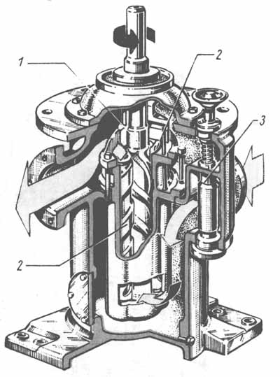
Operating principle of a screw pump
1 - drive shaft; 2 - driven screws; 3 - safety bypass valve
The working principle of a centrifugal pump is shown in the figure below. A characteristic feature of these pumps is a continuous flow of liquid. The working body of the pump, a rotor with blades, is mounted on a rotating pump shaft, which is most often connected directly to the drive motor. The rotating rotor blades transfer the motor's energy to the fluid flowing through the pump, creating pressure that forces the fluid from inlet to outlet. Centrifugal pumps are widely used in ship power plants. They have different designs depending on the power. Thus, the power of pressure pumps for tankers reaches several thousand tons of liquid per hour. If the pumped liquid (for example, water in fire pumps or feed pumps for steam generators) requires higher pressure, multistage pumps are used. The principle of their operation is that water, having reached a certain pressure and leaving the first stage, flows to the suction pipe of the next stage, where the pressure rises again.

Operating principle of a centrifugal pump
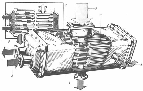
Compressors are machines that compress gases from low inlet pressure to high outlet pressure. The ratio of these two pressures represents the compression ratio. The simplest and most often used compressor on ships is a piston compressor. According to the principle of operation, it is identical to the diesel engine discussed above. Since the temperature of the gases increases during the compression process, a compression ratio of only six to eight can be obtained in the compressor cylinder. A further increase in the compression ratio leads to an increase in temperature, which has a harmful effect on the compressor. If it is necessary to obtain a higher pressure (for example, to start the main engine an air pressure of 2.9 MPa is required), multi-stage compressors are used. Atmospheric pressure air (0.59 MPa) is drawn into the high pressure cylinder with a smaller displacement than that of the low pressure cylinder because the amount of air is reduced due to compression in the low pressure cylinder and cooling in the cooler. The air pressure in the high-pressure cylinder can be increased again by six times. The final air pressure will then be 3.5 MPa.

Operating principle of two-stage air compressor
Along with piston compressors, rotary (centrifugal and axial) and screw compressors are sometimes found on ships. According to the principle of operation, a centrifugal compressor is similar to a centrifugal pump, and a screw compressor is similar to a screw pump), while an axial compressor is more like a turbine. Compressors are used on ships mainly to compress air and gases, for example, coolants in refrigeration units and air conditioning systems. Filters are used to remove mechanical impurities such as dust, small metal particles, sludge and deposits from various liquids and gases. Filters consist of a housing, which most often houses an insert part of the filter, which has the form of metal gratings with the corresponding width of the holes; There are also gaskets made from thin plates (in the slot filter) or from porous materials. To remove particles from magnetic metals, pads made of solid magnets are used.
Purification of fuel and lubricating oils, along with filtration, is carried out using following methods:
Gravity-sedimentation, i.e. settling of impurities heavier than water in tanks;
Centrifugation in separators.
Separators are designed to eliminate impurities that are heavier than the liquid being purified. Their action is based on the centrifugal force that arises. The operating principle of a marine fuel and lubricating oil separator is shown in the figure below. When contaminated oil flows through a tank, all impurities heavier than water (mechanical impurities, dust, metal particles, etc.) are deposited at the bottom of the tank. In this case, the oil is purified using gravity. The cleaning process takes quite a long time and depends on acceleration free fall. To speed up the purification of oil from water and solid impurities, the free fall acceleration is replaced by a significantly higher centrifugal acceleration due to the high rotation speed.

Operating principle of the separator
A - general form; b-e - separation phases. 1 - disc lid; 2 - plate; 3 - drum; 4 - vertical shaft; 5 - electric motor.
Separators are important elements ship power plants. They are used to purify lubricating oils and fuels for engines and steam generators. On new ships separator plants fully automated. Oil separators are used to protect seawater from harmful contaminants, mainly oil residues. Bilge water containing leaked fuel, lubricating oil and other impurities passes through the bilge pump, then through an oil separator, which separates the oil and any impurities that are lighter than water. The water purified in this way is pumped overboard. The operating principle of the oil separator is shown in the figure below. water enters the oil separator, begins to rotate and sinks deeper and deeper into the inside of the device. With the slow movement of water in funnel-shaped tanks, oil particles are separated, that is, they rise or, under the influence of centripetal force, collect near the axis of the oil separator. The separated oil particles rise and are collected in the upper part of the oil separator, from where they are sent to a special waste oil tank. Purified water flows overboard. The contaminated oil is either sent further for recovery or burned in special furnaces, which are increasingly being installed on ships. These ovens destroy all garbage and waste that could contaminate environment. Ships use installations for treating galley, washing and sewage water. The waste water is subjected to strong oxidation and biological neutralization, or the wastewater is thickened and dewatered, and the residues are burned.

Operating principles of the oil separator
1 - funnel-shaped tank; 2 - conical outlet
Water supply systems are tanks in which pressure is created, allowing the water contained there (sea, drinking, washing) to be supplied to all consumers on the ship (water taps, showers, etc.). Water is supplied to the systems using pumps. These pumps are designed in such a way that they can complement the so-called air cushion in water supply systems. The air pumped to maintain the required pressure (from 0.2 to 0.4 MPa) comes from a compressor unit sometimes installed on the ship. Heat exchangers used on ships, depending on. Their purposes are divided into heaters and coolers, condensers and evaporators. Heaters and coolers are used to increase or decrease the temperature of the working media of ship installations. For example, to reduce viscosity, heavy motor fuel is heated before supplying it to the internal combustion engine. In residential and household premises The vessels also heat up the washing water and air. Cool lubricating oil for engines or other machinery, air during compression, fresh water for cooling the main engine, and room air when the ship is in warm climates. Relatively low-pressure water vapor is most often used as a coolant, and sea water is used as a cooling medium. Tubular heat exchangers are mainly used for heating (or cooling). One working medium flows through pipes, and the other through outside pipes inside the housing. The cooler circuit is shown in the figure below. Hot oil flows through pipes located along two walls in a housing shaped like a sheet cylinder. Cooling water follows the pipes. To increase the efficiency of interaction of all working fluids, the flow is passed in waves.

Operating principle of the oil cooler
1 - body; 2 - refrigerator pipes; 3 - oil output; 4 - cooling water outlet; 5 - oil inlet; 6 - cooling water inlet
The heater circuit looks similar. Recently, plate air heaters and coolers have been increasingly used. They have much better heat transfer properties. In capacitors, the working fluid transitions from a gaseous to a liquid state of aggregation. On ships, condensers are used to condense water vapor in the case of water production in a closed steam cycle. The working method of a tubular steam condenser is explained in the following figure. The metal casing contains pipes through which sea water flows through a double circulation circuit.
Operating principle of a capacitor
1 - tubes; 2 - body; 3 - air; 4 - condensation water; 5 - cooling water; 6 - exhaust steam
The exhaust steam, which usually has a low pressure (about 0.005 MPa), leaves the steam turbine through a large outlet, located, for example, on the steam outlet pipe, and rushes to the condenser. The dew point is 32.55°C. At this temperature, the heat of condensation is taken up by the colder sea water. The condensate can be cooled further in a condenser. In modern condensers, condensate subcooling should not exceed 0.5-1.0°C, since it entails heat loss throughout the entire thermal circuit, i.e. steam turbine plant. The air present in the condenser is continuously removed. Used in modern ship power plants with steam turbine capacitors have much more complex design than shown in the figure, but the operating principle is the same. Fresh water is especially valuable on an ocean-going ship, since the supply of fresh water in special tanks is limited. Fresh water is used for both domestic and technical purposes. In addition, it is necessary to compensate for the fresh water circulating in the steam cycle, some of which is lost during operation due to insufficient tightness of valves, turbines, fans, etc.
For this purpose, evaporators are used on ships. They serve both to obtain fresh water from sea water by partial evaporation, and to purify fresh water from tanks by distillation. When fresh water is obtained from sea water, the latter is heated to such an extent that it partially evaporates. The secondary steam thus obtained is supplied to a condenser, in which the finished product is obtained. Residual sea water (brine) with high content salt is thrown overboard. On ships with a steam engine, water vapor is most often used as a coolant in evaporators. In diesel power plants, to increase efficiency, vacuum evaporators are used, heated by waste water from the main engine cooling circuit. In any case, this water must be cooled before it is next supplied to the cooling cavities of the main engine. The water gives off its heat to evaporators, heating sea water to 40-45°C. The water heated in this way in the chamber, where the pressure reaches 0.007-0.008 MPa, begins to partially evaporate, forming secondary steam. As a result of the condensation of secondary steam in the condenser, which together with the evaporator-generator forms a block section, fresh water condensate, i.e. distillate, is obtained.
Ship systems are a set of pipelines, mechanisms, apparatus, instruments, devices and containers provided on ships of all types and purposes and intended for the movement of liquids and gases. The concept of “ship systems” has been entrenched in technical literature since the late 20s of our century.
Ship systems are divided into: general ship systems (Table 1.2), designed to achieve the proper seaworthiness of the vessel, its survivability and unsinkability (bilge and ballast systems, water fire extinguishing systems, irrigation, flooding, etc.) and serving to maintain specified habitability conditions (ventilation systems , air conditioning, domestic fresh water, etc.); systems used during cargo and rescue operations (cargo systems of tankers, tank washing, etc.); power plant systems designed to ensure the operation of power equipment (steam generators, turbines, diesel engines, etc.). Ship systems also include pipelines for various purposes: air, measuring, communication, overflow and bypass pipes, open deck scuppers. Ship systems contain various media - water, air, water vapor, fuel, oil, gases (nitrogen, helium, oxygen , carbon dioxide) and refrigerants - are subjected, if necessary, to heat and moisture (heating, cooling, dehumidification, humidification) and energy (compression, expansion) processing and are supplied to consumers, into containers and removed from them, including overboard. On large modern ships there are 50-60 general ship systems and 20-30 power plant systems.
The ship's pipeline is integral part ship system and is a set of pipes, track, isolation and receiving fittings, fittings, fastening parts, pipe insulation and protection from damage, intended for transporting liquid, gaseous and multiphase media, as well as for transmitting pressure. Ship pipelines appeared on ships of the sailing fleet and served to provide water drainage, supply fresh air and other needs.
Table 1.2. Composition of general ship systems and pipelines for various purposes
Continuation of the table. 1.2

Since 1970, in the technical literature, the term “ship pipeline” has been used to designate ship power plant systems (for example, main steam pipeline, fuel pipeline).
A ship pipeline has a main line through which the transported medium is distributed or collected, and branches through which the transported medium is supplied to or diverted from a group or individual consumers. The highway is made linear, two-line and ring.
Pipelines are made from separate pipes connected to each other by detachable and permanent methods. Pipes made of steel, brass, duralumin, plastic, rubber, copper-based alloys, round and rectangular (in ventilation and air conditioning systems). Detachable connections are flange, coupling, durite and fitting, permanent welded and soldered connections.
To pass through decks and bulkheads, deck and bulkhead glasses, welds and welds are used. In order to compensate for thermal expansion and bending of the ship's hull, compensators (lyre-shaped, bellows, etc.) are installed. To protect pipelines from corrosion, thermal diffusion hot-dip galvanizing and galvanizing are used. steel pipes, oxidation aluminum pipes, silicate-enamel and film-forming (plastic) coatings, provide for the installation of protectors. Pipelines with a cold environment in residential and office premises are insulated with felt, expansite, with a hot environment - Newvel and Sovelite shells, asbestos fabric and pushchnur. The color of the pipeline depends on the purpose of the ship system. Thus, the pipelines of the water fire extinguishing system are painted red, the ballast system - green, the waste water - to match the color of the room with black rings.
Bilge systems are a set of pipelines, mechanisms, apparatus, instruments and devices designed for periodic removal overboard of water accumulating in the hold of a ship and during operation due to leaks in the connections of the hull plating and pipes, sweating, as a result of washing interior spaces(drainage system), as well as for removal overboard from the ship’s premises large mass water received during an accident, damage to the hull or extinguishing a fire (drainage system).
The accumulating water is concentrated in bilges and collection wells, arranged in the double-bottom space in such a way that the drainage system receivers located in them ensure the removal of water when the vessel lists by 15° and trim by 5°. The receivers are protected by nets; in the engine rooms at the water intake, mud boxes are installed in which dirt is deposited. You can use pumps for ballast and other systems. To protect the sea from pollution, oil-containing bilge water is subjected to purification from oil products (separation, sludge) before being discharged overboard. In drainage systems, portable and stationary submersible pumps with a capacity of 1000-2000 m 3 /h are used. Due to the rare use of drainage systems, they are often combined with ballast systems. When stationary and portable water-jet ejectors are used for drainage and dewatering, working water is supplied to them from the water fire extinguishing system. Ships of all types and purposes are equipped with bilge systems in one form or another.
Ballast systems are a set of pipelines, mechanisms, apparatus, instruments, devices and containers designed for receiving water ballast into tanks, pumping and removing it from the vessel for the purpose of changing the draft and stability of the vessel (ballast system) and leveling or creating, if necessary, artificial roll (rolling system) and trim (trimming system) when performing loading and unloading operations, sailing in ice and emergency situations, as well as in connection with the consumption of fuel and water reserves.
Ballast systems appeared on ships in the mid-19th century, when the solid ballast (sand, crushed stone, stones) that had been used was replaced by liquid ballast - sea water. Early 20th century ballast systems were also used to receive and remove fresh water stored in double-bottom tanks.
On large ships, oil ore dumpers, icebreakers, axial pumps, including reversible ones, are used to quickly pump large masses of water in ballast systems, and pipelines are made in the form of hull corridors with unloading channels connected to the atmosphere. The functions of heel and trim systems on a number of ships are carried out by a single ballast system, which on small ships can be combined with bilge systems.
Water fire extinguishing system - a set of pipelines, mechanisms, apparatus, instruments and devices, including receiving kingstons, stationary fire nozzles and fire hoses with portable nozzles, designed to receive water from overboard and supply water to fires in the form of compact or sprayed jets in various premises of the ship and on open decks, as well as on other ships.
Water fire extinguishing systems began to be installed on sailing ships in the 18th century. (with hand water pumps), and to this day they continue to be the main means of fighting fires. In the technical literature, the terms “water extinguishing system” and “water fire extinguishing system” are also found. From the water fire extinguishing system, water is also supplied to the water spray, water curtain, irrigation and sprinkler systems. Provision is made for water selection for the ejectors of the drainage and drainage systems and the flooding system, as well as for various ship needs (washing sewage tanks, anchor chains and fairleads, washing decks and blowing out sea chests).
The pressure line on small ships is linear type, on other ships it is a ring type with several jumpers, separated shut-off valves; Centrifugal pressure pumps with electric or steam drive are distributed among different compartments. Pumps driven by an internal combustion engine are used. Sanitary, ballast, drainage and other seawater pumps can also be used as fire pumps, if oil residues are prevented from getting into the water. Pressure in the pressure line up to 1 MPa; water flow through a portable barrel is up to 7 l/s. On passenger ships carrying more than 36 passengers and ships with increased fire protection, to ensure constant readiness of water fire extinguishing systems for action, the pressure in the line is maintained by the operation of one of the pumps or using a pneumatic tank included in the water fire extinguishing system or in the domestic sea water system. Water fire extinguishing systems are provided on every self-propelled and non-self-propelled vessel that has a power plant with a power of more than 74 kW (100 hp) and a crew of three or more people.
Water spray system - a set of pipelines, instruments and devices designed to supply from overboard and spray water to extinguish fire in engine and boiler rooms, as well as in other ship spaces where liquid fuel is used. The term “deluge system” is also found in the literature. Slot-type water sprayers or deluges installed in the system, unlike sprinklers, do not have a valve and their outlets are constantly open. The water supply is provided from a water fire extinguishing system. Start-up is carried out manually by valves installed in engine rooms, boiler rooms and other rooms; Remote drives are provided to start the system from open decks. Water consumption up to 0.3 l/s per 1 m2 of irrigated area. The water spray system is installed on sea vessels of various classes and purposes.
Irrigation system - a set of pipelines, mechanisms, apparatus, devices and devices designed to supply water to irrigation nozzles when extinguishing a fire or to lower the temperature in storage facilities for flammable substances, in dry cargo rooms, as well as for irrigation purposes in case of fire danger of decks and bulkheads , watches, gatherings, passages, etc. Water is supplied to the irrigation system by water fire extinguishing systems. Unlike sprinkler and water spray systems, water is supplied to the premises in denser jets.
Since the 50s, irrigation systems for storage facilities for explosive and flammable substances have been carried out mainly with automatic start-up
from temperature sensors installed in protected areas and acting on high-speed water supply valves. Automatic start is duplicated by a remote drive from the open deck. The irrigation pipelines of these premises can be constantly filled fresh water, and the pressure in them is maintained using a pneumatic tank, the volume of which ensures the supply of water for the time required for the subsequent supply of sea water from the water fire extinguishing system. The irrigation intensity for storage bulkheads is 0.2 l/s per 1 m perimeter of the irrigated surface, and for racks 0.4 l/s per 1 m2. Water consumption for irrigation of exits, passages is 0.083 l/s per 1 m 2, exit shafts are 0.5 l/s per 1 m of the perimeter of the irrigated surface. Irrigation systems are provided on sea vessels of various classes and purposes.
Sprinkler system is a set of pipelines, mechanisms, apparatus, instruments and devices designed for automatic supply and spraying of water in cabins, wardrooms, salons and service areas of ships at a temperature above a predetermined one, which ensures the prevention or extinguishing of fire. Sprinkler systems with Grinnell heads began to be used on ships before the Second World War. Automatically triggered spray nozzles - sprinklers are placed on the ceilings of protected premises to uniformly cover the entire deck area with torches of finely sprayed water. The deck area irrigated by one sprinkler is up to 9 m2. The system pipelines are constantly filled with fresh water; the pressure in them is maintained using a pneumatic tank, the volume of which ensures the supply of water for the time required for the subsequent supply of sea water from the sprinkler system pump or from the water fire extinguishing system. The water flow through the opened sprinkler is 1.5 l/s, the pressure at the outlet is 0.15 MPa. The opening temperature of sprinklers on ships sailing in temperate zones is 68 °C, in holds 79 °C, in drying rooms and galleys 141 °C. Sprinkler systems are installed on passenger ships carrying more than 36 passengers.
A water curtain system is a set of pipelines, mechanisms, instruments and devices designed to create continuous water curtains that prevent the spread of fire, steam and gases, protect people from thermal radiation, and cool the hull structures of a ship. These systems are combined with a water fire extinguishing system. Water is supplied to slot water sprayers. Water consumption to create 1 m of water curtain is 1.17 l/s. Starting is done manually. Water curtains are installed on rescue ships, fire boats, ferries, etc.
Flooding system is a set of pipelines, apparatus, instruments and devices designed to fill storage areas of explosives and flammable substances with water in the event of a danger of fire and explosion. Flooding systems first appeared on ships of the sailing fleet and served to flood the cruise chambers. Depending on the location of the storage facilities, gravity or forced flooding systems are used. Storage facilities located below the waterline are flooded by gravity under seawater pressure. Storage facilities located above the waterline are forced to flood using water-jet ejectors, to which water is supplied from the water fire extinguishing system, which ensures the suction of large masses of sea water. To release air during flooding, storage facilities are equipped with air pipes.
A steam fire extinguishing system is a set of pipelines, instruments and devices designed to supply water steam to fuel tanks for the purpose of extinguishing burning fuel. The term “steam extinguishing system” is also found in the technical literature. The system uses saturated steam, taken from steam generators and reduced to a pressure of 0.5-1 MPa. Steam fire extinguishing systems ensure that half the volume of protected premises is filled with steam in 15 minutes. The steam supply intensity is 1.33 kg per 1 m3 of room volume. The systems are used on ships with steam generators (main, auxiliary, recovery boilers, etc.).
An inert gas system is a set of pipelines, mechanisms, instruments, devices and containers designed for cooling, cleaning from soot and sulfur oxides, drying and supplying flue gases to the cargo spaces of oil tankers, oil dumpers and gas carriers in order to create an explosion- and fire-proof atmosphere with low (up to 5-6%) oxygen content. Before the Second World War it was known as the Harker system. In the USSR, the first inert gas system was installed in 1952 on the river steamer Volodarsky. This system became widespread in the 60s with the advent of large-tonnage tankers and gas carriers.
Gases are taken from the chimneys of the main and auxiliary boilers (less often from the chimneys of diesel engines) or produced in autonomous generators. Gases are purified and cooled using sea water in contact devices (scrubbers with an irrigated nozzle, cyclone-foam scrubbers, etc.). To improve gas purification from sulfur oxides, alkaline solutions can be added to sea water. On gas carriers, after cleaning and cooling, flue gases are dried using refrigeration machines and adsorbents, which prevents freezing of moisture in the cargo space. In accordance with the rules of the International Maritime Organization (ICMO), all oil tankers and vessels for transporting petroleum products with a deadweight of over 20 thousand tons are equipped with systems inert gases. The calculations for these systems largely depend on their type.
Drinking water system - a set of pipelines, mechanisms, apparatus, instruments, devices and containers designed for receiving, storing, disinfecting, mineralizing and supplying drinking water to galleys, drinking lagoons, saturators, buffets and other places of its consumption, as well as for transferring drinking water water to other ships.
The simplest drinking water systems were used on ships of the sailing fleet. Work on creating drinking water systems on ships of the Russian fleet began in the mid-19th century. They underwent intensive improvement in the 50s of our century.
Fresh water from the shore, from another vessel or from a desalination plant enters a reserve tank, from where it is pumped into a pneumatic tank, undergoing disinfection and mineralization if necessary, and then under pressure to consumers. Spare tanks are often built into the ship's hull; their surface is protected cement mortar, synthetic materials and paints. A vertical cylindrical pneumatic tank is partially filled with water and compressed air, and has a pressure switch that affects the start of the pump when the water level in it decreases. Disinfection is carried out by chlorination, ultraviolet irradiation using bactericidal lamps treatment with silver in ionizers, ozonation of water, mineralization - adding solutions of salts and alkalis. Drinking water systems on some ships are combined with washing water systems in common system household fresh water. On sea vessels of unlimited navigation area, the consumption of drinking water per person per day is 40 liters or more (on passenger ships 80-90 liters).
Washing water system - a set of pipelines, mechanisms, apparatus, instruments, devices and containers designed for receiving, storing, disinfecting, heating and supplying showers, baths, baths, laundries, washbasins and other places of consumption of cold and hot fresh washing water and for transferring it to other vessels. These systems began to be used on ships at the end of the 19th century.
Supplies of washing water are stored in side or bottom tanks, in forepeaks, afterpeaks and other compartments of the vessel. The washing water system differs from the drinking water system by the presence of a water heater, tank, pump and hot water pipeline. Water is heated to 60-70 °C by steam. The set heating temperature is maintained automatically by a sensor located in the hot water tank and acting on the steam valve. Washbasins are supplied with washing water, purified and disinfected in the same way as drinking water. On some ships, washing water systems are combined with drinking water systems to form a common domestic fresh water system. On seagoing vessels of unlimited navigation area, the consumption of washing water per person per day is 60 liters or more (on passenger vessels 120-150 liters).
A domestic fresh water system is a set of pipelines, mechanisms, apparatus, instruments, devices designed for receiving, storing, sanitary and hygienic treatment and supplying fresh water to places of consumption necessary for drinking, cooking, washing, laundry and other domestic needs. These systems are used on ships where there are no separate systems drinking and washing water. The systems also ensure the transfer of fresh water to other vessels. Domestic fresh water systems appeared in the 60s, mainly on fishing vessels of small and medium displacement. If they are used, the possibility of using washing water for drinking is eliminated, the length of pipelines is reduced, and the number of fittings and tanks is reduced. Fresh water consumption on passenger ships is 200-240 liters per day per person.
The domestic sea water system is a set of pipelines, mechanisms, apparatus, instruments and devices intended for supplying"
sea water to sanitary equipment: for washing toilet basins and urinals, for potato washers, for cooling water heaters and boilers, and for other consumers. The water received from overboard is pumped into a pneumatic tank, from where it is sent to places of consumption. There are no spare tanks. On some ships, jumpers are provided between the domestic sea water system and the washing water system for washing with sea water when sailing on the open sea, as well as the water fire extinguishing system - to maintain constant water pressure in the latter.
Sewage systems are a set of pipelines, mechanisms, apparatus, instruments, devices and containers designed for collecting, processing (cleaning and disinfection) and removing fecal and waste water from latrines, medical premises and premises for transporting animals, as well as for collecting and removal from the vessel of domestic water from washrooms, baths, laundries, galleys and other utility rooms.
The simplest sewage systems first appeared on ships of the sailing fleet. In the technical literature, the term “wastewater systems” is also used. Work to improve wastewater systems began in the 70s due to stricter requirements for protecting the marine environment from pollution.
Fecal, waste and household water when sailing on the open sea are removed overboard by gravity through pipelines laid with a slope towards the side. Storm flaps are installed at the side openings located above the waterline to prevent the reverse movement of sewage when the outlets are immersed in water under rolling conditions. When the ship is in coastal waters and docked at a port, fecal and domestic waters are cleaned and disinfected by chemical, electrochemical or biological methods before being discharged overboard. In the absence of devices for cleaning and disinfection, they are collected in tanks, after which they are pumped into floating or coastal tanks or discharged into the open sea.
Open deck scuppers are a set of pipelines with receivers designed to drain overboard water entering the open decks during rough seas, due to precipitation, when extinguishing fires, cleaning, etc. Scupper receivers are installed in places where water may accumulate. From the scuppers, water is drained by gravity through scupper pipes to the underlying open decks or directly overboard. Open deck scuppers are provided on multi-deck ships and those with superstructures.
Ventilation system is a set of pipelines, mechanisms, instruments and devices designed to receive and supply outside air to the ship’s premises and remove contaminated air from them in order to ensure air exchange and air mobility.
The first ventilation systems in the form of “windsails”, through which air entered the premises, were used on sailing warships. Invented in 1741, a ship's “ventilator” with bellows and a wooden centrifugal fan With manual drive described by P. Ya. Gamaley in 1804 Much attention ventilation systems were paid attention to in the Russian fleet from the second half of the 19th century.
Air exchange is carried out naturally with the help of rotary deflectors and ejection heads installed on open decks and superstructures, and forced (artificially) with centrifugal and axial fans.
Reception of outside air and removal of contaminated air during forced ventilation are produced through deck mushroom-shaped heads or shafts having louvers and placed in superstructures or chimney casings.
Latrine, washbasins, showers, bathrooms, laundries, battery rooms and other rooms where vapors and gases are emitted are equipped with exhaust ventilation systems with air suction from the premises, and cabins, cockpits and service rooms (in the absence of comfortable air conditioning systems) are equipped with supply systems with exit of polluted air through the door grilles into the corridor. Mixed supply and exhaust systems equip engine and boiler rooms, equipment and cargo rooms (in the absence of a technical air conditioning system). To reduce noise, fans are placed in enclosures, and sound-absorbing inserts are installed in pipelines. Ventilation systems are used on ships of all classes and purposes.
Comfortable air conditioning system - a set of pipelines, mechanisms, apparatus, instruments and devices designed for receiving, heating, cooling, humidifying air and supplying it to cabins, wardrooms, lounges, cockpits, medical and service areas of the ship, which ensures the maintenance of they include air parameters favorable for people’s well-being: temperature (when swimming in the tropics 25-28°C), humidity (40-60%), mobility (up to 0.5 m/s) and gas composition - regardless of external conditions.
These systems first appeared on ships at the end of the 19th century. By 1930, there were about 100 ships in the world equipped with comfort air conditioning systems. Their rapid development began in the late 50s.
Mechanisms (fans) and devices (heaters and coolers, humidifiers) are assembled in a central air conditioner. Water steam is supplied to the heaters under a pressure of 0.3-0.5 MPa or hot water, to coolers - cold water or refrigerant (freon) from a refrigeration machine. From the central air conditioner to the air distributors installed in the rooms, air flows through one or two channels. The speed in the channels is 18-20 m/s. In single-channel systems, heat exchangers can be built into the air distributors for additional air heating (steam, water or electric). In two-channel systems, air enters the air distributors at different temperatures, which allows it to be mixed in the desired proportion. The intake of outside air and the removal of contaminated air are carried out in the same way as in the ventilation system. Currently, sea vessels of all classes and purposes are equipped with comfortable air conditioning systems.
Technical air conditioning system is a set of pipelines, mechanisms, apparatus, instruments and devices intended for receiving, heating, cooling, drying air and supplying it to the cargo and other spaces of the ship, which ensures that the specified air parameters are maintained in them, regardless of external conditions. environments required to preserve cargo or operate equipment, instruments, etc., as well as to reduce corrosion of metal hull structures.
The first samples of ship dehumidifiers for technical air conditioning appeared in the late 30s of our century. Technical air conditioning systems became widespread in the late 50s.
Air dehumidification is carried out by solid water absorbers (adsorbents), liquid (absorbents), and also by cooling using a refrigeration machine. Silica gel and zeolite are used as adsorbents, salt solutions are used as absorbents - chloride, less often lithium bromide; fibrous materials impregnated with salt solutions are used.
Dried and cooled air is supplied by fans to cargo spaces, instruments and other equipment. To remove water from absorbers (desorption), additional fans are installed. The intake of outside air and its removal from the premises are carried out similarly to those provided for in ventilation systems.
Steam heating systems are a set of pipelines, apparatus, instruments and devices designed to supply water steam to heating devices- steam heaters and removal of exhaust steam and condensate from them, which provides heating of ship premises.
Before the Second World War, these systems were the main means of heating the residential and office spaces of ships. With the advent of comfortable air conditioning systems in the 50s, they began to be used mainly for heating engine and boiler rooms (when the ship is moored), mechanical workshops, utility storerooms, sanitary and sanitary premises, corridors and vestibules.
Single-line systems are used in which fresh, exhaust steam and condensate move through one pipeline. Behind the heaters, steam traps are float-type, thermostatic with bellows or membranes, and thermodynamic. Steel or copper heating pads in the form of finned tubes are installed with easily removable casings, the surface temperature of which does not exceed 70 °C. Fresh steam pressure up to 0.3 MPa, temperature 130-135 °C. Steam heating systems are used on most self-propelled ships that have steam generators.
Rescue ship systems are a set of pipelines, mechanisms, apparatus, instruments, devices and containers designed to perform certain functions on rescue ships: erosion of soil with water jets around a sunken ship or one sitting on the ground, suction of soil (sand and silt) from the premises of a sunken ship vessel, pumping water from the flooded premises of a damaged vessel, receiving, storing and supplying compressed gases (nitrogen, helium and oxygen), preparing and supplying gas mixtures for diving work and charging breathing apparatus cylinders. Rescue ships are also equipped with water fire extinguishing systems, water curtains and other means of fighting fires.
Tanker systems are a set of pipelines, mechanisms, apparatus, instruments, devices and containers designed for receiving, pumping within the vessel and unloading liquid cargo (cargo system), pumping unselected cargo from cargo tanks cargo system liquid cargo (cleaning system), maintaining safe pressure and gas exchange in tanks during the process of receiving, issuing and transporting liquid cargo (gas exhaust system), supplying detergent composition to washing machines (hydromonitors) and subsequent removal of washing products from cargo tanks (tank washing system) , irrigation of the outer surfaces of cargo tanks with sea water in order to reduce the temperature of the cargo and reduce its losses from evaporation (cargo tank irrigation system). The term “special oil tanker systems” is also used in the literature.
Load centrifugal and stripping piston pumps located in the pump room. The mains are laid in the bottom corridor and along the cargo deck. Tank washing is carried out with crude oil and heated sea water with a detergent composition. Liquid tanker systems are used on tankers and oil drying vessels carrying oil.
Air pipes are a set of pipelines and devices designed to communicate with the atmosphere of liquid-filled tanks, cofferdams and other compartments of the vessel. The upper ends of the pipes leading to the open decks are bent 180°, as a result of which they form a “jib”, or are equipped with protective caps or shut-off floats to prevent water from entering them during a wave attack. The air pipes of fuel and oil tanks have fire-barrier mesh - flame arresters, the air pipes of tanks with drinking and washing water - dust filters. The diameter of the pipes is 50 mm and above, they can be combined with measuring pipes.
Measuring pipes are a set of pipelines and devices designed to measure liquid levels in tanks, cisterns, bilges, cofferdams and other storage facilities. Measuring pipes with graduated slats (foot rods) placed in them are the simplest devices that were used on ships of the sailing fleet. Measuring pipes are installed on decks or double bottom flooring in places convenient for measurements. They are closed with a lid on top. The liquid level is determined by the wetted surface of the rack. Measuring pipes can be combined with air pipes.
Talking pipes are a set of pipelines and devices intended for internal voice communication carried out by personnel between the premises or posts of the ship. They are the simplest means for transmitting commands and information. The end branches of the speaking pipes are equipped with a megaphone and a whistle for giving a call signal. Along with the use of radio communications, many modern ships are also equipped with speaking pipes.
End of work -
This topic belongs to the section:
GENERAL SHIP SYSTEMS, THEIR OPERATION AND MANAGEMENT
On the website read: "GENERAL COURT SYSTEMS, THEIR OPERATION AND MANAGEMENT"
If you need additional material on this topic, or you did not find what you were looking for, we recommend using the search in our database of works:
What will we do with the received material:
If this material was useful to you, you can save it to your page on social networks: