Taking into account the conditions and nature of the operation of open gears (insufficient protection from contamination by abrasive particles and increased abrasive wear with poor lubrication, large deformations of the shafts, which leads to an increase in clearances in the mesh, an increase in dynamic loads, a decrease in the strength of worn teeth due to a decrease in their cross-sectional area and , as a consequence, to tooth breakage), it is recommended to calculate transmission data using bending stresses. In these gears, chipping is not observed because the surface layers of the teeth are worn out and removed before fatigue cracks appear.
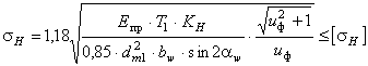
For the design calculation of open gears based on bending stresses, the engagement modulus is determined from the expressions:
− for spur wheels
− for helical wheels
Here: z 3 – number of open gear teeth (see source data);
− the coefficient of the width of the wheel ring gear relative to the initial diameter of the gear is recommended to be set for open gears = 0.1…2.0;
− the permissible bending stress of the gear teeth, N/mm 2, is determined in accordance with clause 2.3. (“Calculation of permissible stresses”);
T 3 – torque on the gear, Nm; ;
−see above, for design calculations take = 0.8;
−see fig. 2.3;
Y F 3 - see table. 2.9.
The resulting module value is rounded up to a value from the standard series of modules (see clause 2.5).
Knowing the value of the module, the geometric dimensions of the gear are determined:
pitch diameter − or
tooth tip diameter − ![]()
tooth root diameter − ![]()
crown width −
The accuracy of calculating gear diameters is up to 0.001 mm, the value of the width of the ring gear is rounded to an integer according to normal linear dimensions (see Table 2.5). The verification calculation of such a transmission based on contact stresses is performed in accordance with clause 2.6. (“Verification calculation of a closed spur gear”).
2.8. Calculation of a closed bevel gear
The most widely used in gear manufacturing are spur bevel gears, in which the shaft axes intersect at an angle (Fig. 2.4), the so-called orthogonal gears.

Rice. 2.4
Design calculation
The main overall dimension of the gear - the pitch diameter of the wheel at the outer end - is calculated using the formula:
 ,
,
Where E ![]() MPa;
MPa;
T 2 – torque on the wheel shaft, Nmm (see paragraph 2.4);
− coefficient of uneven distribution of load along the length of the tooth is determined from the graphs in Fig. 2.5.
Here TO be− ratio of the width of the ring gear relative to the outer cone distance, TO be = b w / R e. Recommended to take. Smaller values are assigned for non-running gears when H 1 and H 2 > 350 HB or V> 15 m/s.

Rice. 2.5
The most common value in gear manufacturing is TO be= 0.285, then the previous expression for determining pitch diameter along the outer end of the wheel takes the form
 ,
,
Where u p – calculated gear ratio bevel gear, or u p = z 2 / z 1 .
Geometric calculation
Determine the pitch diameter of the gear along the outer end.
The number of gear teeth is determined by the value:
At N 1 and ,
At N 1 and .
Calculated value z 1 is rounded to the nearest whole number.

Rice. 2.6
Determine the number of wheel teeth.
The calculated value is rounded to a whole number. After this you need to clarify:
Transmission ratio,
Wheel pitch cone angle,
Gear pitch cone angle,
External circumferential module ![]() .
.
It is recommended to round m e before standard value m e f for a number of modules: 1.5; 2; 2.5; 3; 4; 5; 6; 8; 10. After this, the diameter values are specified ![]() And
And ![]() .
.
Calculate the value of the external conical transmission distance (Fig. 2.4).
The working width of the wheel ring gear is determined as .
The resulting value is rounded to the nearest normal value. linear dimensions(Table 2.5).
Determine the design modulus of engagement in the middle section of the tooth
In this case, the found value m m don't round!
Calculate the external height of the tooth head.
The external height of the tooth stem is determined as .
The outer diameter of the tops of the wheel teeth is calculated using the formula.
The angle of the tooth stem is calculated using the formula ![]() .
.
Verification calculation
When calculating the endurance of wheel teeth using contact stresses, the fulfillment of the condition is checked
 ,
,
Where E pr - reduced modulus of elasticity, for steel wheels ![]() MPa;
MPa;
−torque on the gear, Nmm, ;
Introduction……………..…………………………………..……………..2
1. Analysis of the kinematic scheme…………..……..………………..2
2. Kinematic calculation of the drive…………………………………3
3. Determination of geometric parameters of a cylindrical
gear transmission………………………………………….…………..6
4. Geometric calculation of bevel gear drive………9
5. Determination of geometric dimensions and calculations for
strength of the output shaft…………………………………………………………….11
6. Test calculation of the bearing..…………………………….16
7. List of references……………………………..18
A gearbox is a mechanism consisting of gear or worm
gears enclosed in a separate closed housing. Gearbox
designed to reduce the speed and, accordingly, increase the torque.
Gearboxes are divided according to the following characteristics:
By type of transmission - gear, worm or gear-worm:
According to the number of stages - single-stage (when transmission is carried out by one pair of wheels), two-, three- or multi-stage:
Type gear wheels- cylindrical, conical, or conical-cylindrical;
According to the location of the gearbox shafts in space - horizontal, vertical, inclined:
According to the peculiarities of the kinematic scheme, “unfolded, coaxial, with a bifurcated stage.
1. Analysis of the kinematic scheme
Our mechanism consists of an electric machine drive (1), a clutch (2), a spur gear (3), cylindrical wheels (4), bevel gear(5), bevel wheel (6), shafts (7,6,9) and three pairs of rolling bearings. Power on driven shaft N 3 =9.2 kW, angular velocity n 3 = 155 rpm, the drive is designed for long work, permissible speed deviation
5%,
2. Kinematic calculation of the drive
2.1. Determining the overall efficiency of the drive
h=h 1 *h 2 *h 3 3 *h 4According to table 5 (1) we have
h 1 =0.93 - efficiency of spur gear;
h 2 =0.9 - efficiency conical transfers;
h 3 =0.98 - efficiency of rolling bearings;
h 4 =0.98 - coupling efficiency
h = 0.93 * 0.98 3 * 0.9 * 0.98 = 0.77
2.2. Determining the rated power of the engine
N dv =N 3 /h=11.9 kW
2.3. Select the engine type according to table 13 (2). This is the engine
A62 with the nearest higher power value 14 kW. This rated power value corresponds to a rotation speed of 1500 rpm.
2.4. Determining the drive gear ratio
i = i nom /n 3 = 1500/155 = 9.78
2.5. Since our mechanism consists of a closed cylindrical gear and an open bevel gear, we divide the gear ratio into two components:
2.6. We specify the total gear ratio
i = g.5 * 4 = 10
2.7. We determine the maximum tolerance output shaft speed
- permissible speed deviation according to the specification.2.8. Permissible output shaft rotation speed taking into account deviations
2.9. Knowing the particular gear ratios, we determine the rotation frequency of each shaft:
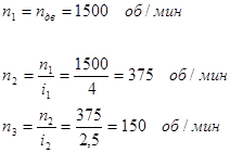
Thus, the output shaft rotation speed is within acceptable limits.
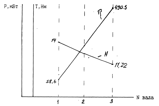
2.10. We determine the torques transmitted by the mechanism shafts, taking into account gear ratios and efficiency:

2.11 Similarly, we determine the power transmitted by the shafts
2.12. Let's plot the distribution of torque and power along the drive shafts
3. Definition geometric parameters of cylindrical gear transmission
3.1. For wheels with a standard initial contour, cut without offset cutting tool(x = 0), it is recommended to select the number of gear teeth in the range from 22 to 26. Select Z 1 = 22
3.2. Number of wheel teeth:
Z 2 = Z 1 * i 1 = 22 * 4 = 88
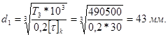
3.3. We determine the center distance using the formula

where K a is the auxiliary coefficient, for helical gears it is 43;
- the coefficient of the width of the gear rim located symmetrically relative to the supports, according to table 9(3) is equal to 0.4; - gear ratio;T 2 - torque on the low-speed shaft;
Using Table 3.1 (3), we determine the steel grade for the gear - 40X. hardness > 45HRC: for the wheel - 40X. hardness
350NV.According to table 3.2 (3) for gear
The resulting value of the center distance for non-standard gears is rounded to the nearest of the range of normal linear dimensions, A W = 100 mm.
3.4. We determine the engagement modulus using the formula
where K m is the auxiliary coefficient, for helical gears it is equal to 5.8;
The resulting module value is rounded up to the standard value from the series p. 59 (3). For power gears with a hardness of one of the wheels > 45HRC. Module > 1.5 is accepted. therefore we accept the module m=2.
3.5. We determine the angle of inclination of the teeth for helical gears:
3.6. Determine the total number of gear teeth and wheels for helical gears
We round the resulting value down to a whole number, that is, Z = 100.
3.7. Determining the number of gear teeth
3.8. Determining the number of wheel teeth
Z 2 = Z - Z 1 = 100 - 20 == 80
3.9. Determine the actual gear ratio and check its deviation
Therefore, the gear ratio is chosen correctly.
3.10. We determine the main geometric parameters transmissions and put them in a table
| Options | Formulas | Wheel | |
| 1 | Number of teeth | Z 2 | 80 |
| 2 | Normal module, mm | m n =m | 2 |
| 3 | Normal pitch, mm | 6,28 | |
| 4 | Angle of original contour | ||
| 5 | Tooth angle | ||
| 6 | End module, mm | 2,03 | |
| 7 | Face pitch, mm | 2,03 | |
| 8 | Tooth head coefficient | H | 1 |
| 9 | Tooth root coefficient | With rn > 1 | 0.25 |
| 10 | Diameter pitch circle, mm | d = Z * m t | 162.4 |
| 11 | Height dividing head tooth, mm | h a = h * m | 2 |
| 12 | Height of tooth dividing leg, mm | H f = (h + C)*m | 2,5 |
| 13 | Tooth height, mm | h = h a + h f | 4.5 |
| l4 | Protrusion circle diameter, mm |
d a = d + 2 h a | 166.4 |
| 15 | Diameter of the circle of the depressions, mm | d f =d - 2h f | 155,4 |
| 16 | Center distance, mm | A = 0.5 (d 1 + d 2) | 100 |
| 17 | Crown width, mm | 40 |
4. Geometric calculation of bevel gear
4.1 Determine the pitch diameter of the wheel

V H - coefficient of the type of bevel gears, for spur gears it is equal to 1.

We round the resulting value of the outer pitch diameter of the wheel to the nearest value from the range of normal linear dimensions in Table 13.15 (3).
d e4 =250 mm
4.2. Determine the angles of the pitch cones of the gear and wheel
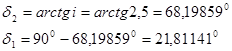
4.3. Determining the outer cone distance
4.4. Determining the width of the ring gear

4.5. Defining the outer circumferential module
where K f b is a coefficient that takes into account the distribution of load across the width of the rim, equal to 1; (3)
V f = 0.85 - coefficient of the type of bevel wheels. (3)
Since the gear is open, we increase the module value by 30%, that is, m = 5 mm.
4.6. Determine the number of teeth of the wheel and gear

4.7. Determine the actual gear ratio.
4.8. Determine the outer diameters of the gear and wheel:
divisive
;tooth tips
=109.28 mm; = 253.71 mm;tooth cavities
mean pitch diameter
=85,7mm;5. Determination of geometric dimensions and calculation of the strength of the output shaft
5.1. We determine the forces acting in the engagement of a bevel spur gear:
circumferential
radial
= 612 N, = 1530 N.5.2 Select the material for the shaft according to table 3.2 (3). This is 45 improved steel, with the following mechanical characteristics:
permissible torsional stress
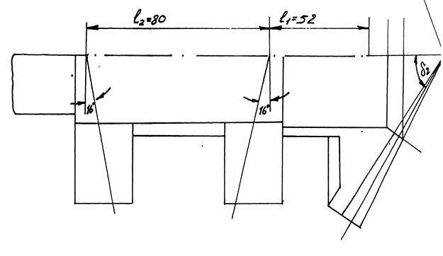
5.3. We roughly determine geometric dimensions each shaft stage:
Outlet diameter
We take d 1 = 45 mm.
Based on this, we take the diameter under the bearing d 2 = 50 mm.
5.4. We pre-select rolling bearings. According to table 7.2 (3) for bevel gear at n<1500 об/мин применяется подшипник роликовый конический однорядный. Выбираем типоразмер подшипника по величине диаметра внутреннего кольца, равного диаметру d 2 = 50мм. Это подшипник легкой широкой серии 7510: d = 50мм, D = 90мм, Т = 25 мм, угол контакта 16 0 , C r =62 kH.
5.5. We draw the shaft steps according to the dimensions obtained in the approximate calculation and determine the distances between the points of application of the bearing reactions.
5.6. We draw a diagram of the forces in the bevel gear engagement.
5.7. We determine the reactions of the supports:
a) vertical plane
b) construct a diagram of bending moments in characteristic sections A, B, C (rice. 5.1)
c) horizontal plane,
ASSESSMENT OF THE PERFORMANCE OF CYLINDRICAL GEARS
PLAN LECTIONS
1. Operating conditions.
2. Calculated specific loads.
3. Gear design algorithm.
4. Calculations of gears for contact strength. Program
5. Determination of stresses during tooth bending. ZUCF program.
6. Features of calculations of helical and chevron cylindrical gears.
1. Operating Conditions
The transfer of load in a gear train occurs as a result of the contact of the side profiles of the mating teeth. Under the influence of pressure forces, the teeth are in a complexly stressed state. In this case, both the surface of the teeth (linear contact) and the entire volume of the tooth are loaded. Therefore, the performance of the gear is assessed by the contact strength of the lateral surface of the teeth and the volumetric strength of the tooth under complex loading. Assessment of tooth strength is complicated by the action of variable load on the tooth, changing in an intermittent pulsating cycle.
If the contact strength of the tooth surface is insufficient, fatigue chipping of the working surfaces occurs.
Failures of teeth are also mainly of a fatigue nature and occur either when the gear is overloaded or when their volumetric strength is insufficient. When teeth are subjected to volumetric loading, the main type of deformation is bending. Therefore, the assessment of the volumetric strength of teeth is usually carried out by bending deformation. Thus, in gear drives, when assessing performance, two conditions are used:
a) condition of surface contact strength
Conditions for optimizing transmission parameters. Standard involute
This gear transmission ensures continuity of tooth contact during operation and a constant gear ratio within the permissible range
errors. For such a transmission, the main criterion for performance is ensuring the contact and bending strength of the teeth. Therefore, the main optimization objective function for closed gears will be expressed by the condition of the contact strength of the tooth surface with an acceptable 20% underload of the gear and its 10% overload, i.e.
0.8H /H 1.1,
where H is the actual contact stress on the tooth surface, N/mm2;H is the permissible contact stress for the wheel material.
Such an objective function, due to the impossibility of a unique solution, has a large number of options.
At the same time, it is desirable to introduce a number of additional design and operating conditions for the gear transmission: ensuring optimal bending strength of the teeth, minimum overall dimensions and weight, standard modulus and center distance, minimum deviation of the gear ratio, minimum moment of inertia of the transmission, etc. Such additional conditions make it possible to introduce additional limiting functions into the calculation and thereby reduce the number of undetectable influence parameters.
In the method under consideration, the following conditions of restrictive functions are introduced:
Optimal tooth bending strength: for gears
0.8 F w/F w 0.1,
for wheel
0.8 F to /F to 1.1;
minimum number of teeth;
minimum deviation of the gear ratio;
providing standard values of module and center distance;
reducing to a minimum the uneven distribution of load along the length of the tooth by minimizing the width of the crown;
minimum angle of inclination of teeth from the condition of end overlap;
minimum mass and moment of inertia of the wheels;
optimal tool displacement coefficients based on the condition of greatest tooth strength;
optimal hardness and grade of material depending on operating conditions. It is necessary to introduce a number of essential elements into the operating conditions
additions that take into account the specific loading, design and operating conditions of gears.
2. Calculated specific loads
When drawing up design diagrams for gear drives, the load schematization is performed by introducing the calculated specific load, which is understood as the value of the conditional load from the circumferential force F t per unit working width of the gear. If we denote the design specific load by q, then its value can be determined from the expression
where K is the load factor; b w is the working width of the gear. The load factor is introduced to compensate for unaccounted
additional stresses arising due to complex loading of the teeth, design features and operation of the wheels. The problem of choosing the value of the load factor in gears is one of the complex ones.
According to the methodology for calculating involute gears recommended by GOST 21354–75, the load factor values are determined according to the following dependencies:
K HK Hβ K Hα K Hv, | K FK Fβ K Fα K Fv, |
where K H β ,K F β are the coefficients of load concentration along the width of the gear rim, respectively, for contact endurance and bending; K H α ,K F α - coefficients that take into account the distribution of load between the teeth, respectively, for contact endurance and bending; K H ν , K F ν - coefficients that take into account dynamic load in engagement, respectively, during contact endurance and bending.
To determine the values of the coefficients, the reference literature provides the corresponding graphs, tables, formulas and approximating dependencies. Let's look at these dependencies.
The load distribution coefficient between the teeth is determined by the dependencies for helical gears:
K H α (0.0026ST 0.013)v 0.027ST 0.84;
KF α | 4 εα | 1 ST 5 | |
4εα |
|||
where ST is the degree of transmission accuracy; v is the peripheral speed of the teeth; εα – end overlap coefficient.
For spur gears, the values of both coefficients are assumed to be equal to unity.
![]()
Table 6.1 |
||||
Values of coefficients H and F | ||||
Type of transmission | Odds | Surface hardness |
||
Straight | ||||
Helical | ||||
During design calculations, when the dimensions of the wheels are unknown, the peripheral speed can be approximately determined by the formula
where q Hv ,q Fv – specific circumferential dynamic forces, N/mm. The values of these forces must satisfy the following relationships:
qHv δ H g0 vaw i qpred ;
qFv δ F g0 vaw i qpred .
Here H,F are coefficients that take into account the type of gear transmission (Table 6.1); g 0 is a coefficient that takes into account the influence of the difference in the circumferential pitches of the wheels;
The values of the load concentration coefficients along the width of the ring gear depend on the coefficient of the width of the ring gear bd =b w /d w and the number of the scheme according to which the wheels were mounted:
with tooth surface hardness HB 350
KH = 1 + 0.51bd /NS ; |

with hardness HB > 350 | ||
KH = 1 + 1.1bd /NS ; | KF = 1 + 1.8bd/NS, |
where NS is the scheme number, taking into account the location of the wheels and other transmission characteristics relative to the supports.
3. Calculations of gears for contact strength.
When assessing performance according to the contact endurance condition (6.1), it is necessary to calculate the actual contact stresses arising on the side surfaces of the teeth.
Experimental studies show that the destruction of tooth profiles begins in places located in the zone of the initial circles. To determine contact stresses, you can use the Hertz–Belyaev formula to calculate the maximum normal stress in the contact zone of two cylinders along a linear contact:
where is the reduced modulus of elasticity; ρ – reduced radius of curvature of the surface; µ – Poisson's ratio.
To take into account the specific loading and operating conditions of gears, it is necessary to introduce a number of additions into formula (6.13).
Let us determine the voltage for the gear transmission at the moment when the point of contact of the teeth is at the engagement pole P (Fig. 6.2).
We will find the intensity of the load q with which the wheel teeth are pressed against each other if we divide the total design pressure force F n by the length of the contact line l, i.e.
q = Fn/l.
For a transmission with oblique teeth, we determine the total design pressure force of the teeth through the circumferential force F t and the load factor K H:
F tK H | |||
where α is the tooth profile angle; β – tooth inclination angle.
Considering that in a helical gearing the length of the tooth l depends on its inclination angle β, the wheel widthb w and the tooth overlap coefficient, we rewrite relationship (6.3) in the following form:
F tK Hcosβ | F tK H | ||||||||||||||||||||||||||||||
cos α cosβ b K | cosα b K | ||||||||||||||||||||||||||||||
where K | - coefficient | degree of overlap; | spur gears |
||||||||||||||||||||||||||||
For helical gears K = . | |||||||||||||||||||||||||||||||
Let us denote q | Then the previous dependence will take the form |
||||||||||||||||||||||||||||||
q qt | |||||||||||||||||||||||||||||||
cos α K | |||||||||||||||||||||||||||||||
When the teeth touch at the pole, the radii of curvature of the involutes |
|||||||||||||||||||||||||||||||
teeth 1 =N 1 and | N 2. | ρ1 O 1 P sin α |
|||||||||||||||||||||||||||||
Considering, | ∆О 1 N 1 P and ∆О 2 N 2 P (Fig. | ||||||||||||||||||||||||||||||
and ρ2 O 2 P sin α , | let's define | given | curvature | conjugate |
|||||||||||||||||||||||||||
surfaces: | |||||||||||||||||||||||||||||||
ρ1 ρ2 | d w 1 sin αd w 2 sin α | ||||||||||||||||||||||||||||||
sin α |
|||||||||||||||||||||||||||||||
2cosβ | |||||||||||||||||||||||||||||||
where d w 1 and d w 2 are the initial diameters of the first and second wheels; d w 1 =O 1 P and d w 2 =O 2 P; The plus sign is used for external gearing; minus sign – for internal.
After appropriate transformations we get
d w 1 sin αi | ||||||||||||||||||||||||
2 i 1 cosβ | ||||||||||||||||||||||||
Let us substitute the values of q and ρ from expressions (6.15) and (6.17) into the dependence |
||||||||||||||||||||||||
(6.14) we get | ||||||||||||||||||||||||
ζH 0.418 | q i E 2i 1 cosβ | |||||||||||||||||||||||
cos α K ε 1 μ2 | d w 1 sin αi |
|||||||||||||||||||||||
For practical calculations according to GOST 21354–75, the following are introduced: |
||||||||||||||||||||||||
legend: | ||||||||||||||||||||||||
– coefficient taking into account mechanical properties |
||||||||||||||||||||||||
mating gear materials; | ||||||||||||||||||||||||
– coefficient taking into account the shape | conjugate |
|||||||||||||||||||||||
tooth surfaces in the engagement pole; | ||||||||||||||||||||||||
Z ε1/ K ε | – coefficient taking into account the total length of the contact |
|||||||||||||||||||||||
ny lines. | ||||||||||||||||||||||||
Taking into account these notations, dependence (6.18) takes the form | ||||||||||||||||||||||||
ζ HZ m Z HZ ε | qi i1 | |||||||||||||||||||||||
dw 1 i | ||||||||||||||||||||||||
Formula (6.19) allows you to calculate contact stresses for spur and helical gears of external and internal gears.
4. Determination of stresses during tooth bending
When assessing bending stresses, it is assumed that the tooth of the driven wheel experiences the greatest stress at the beginning of engagement, and the entire load is transmitted by one pair of teeth during the entire period of engagement. Experimental studies show that manufacturing errors leading to discrepancies in circumferential pitches are not fully compensated by tooth deformations. As a result, the teeth will be most loaded at the beginning and end of engagement.
The design diagram of the tooth can be represented as a rigidly clamped beam loaded with a normal force F applied to the top of the tooth (Fig. 6.3). The resulting friction force Ftr between the teeth leads to deflection

strength normal pressure to the friction angle. The magnitude of the force F" is found by the formula
F" =F /cos. |
Using schematization techniques, we draw coordinate axes xOz, moving the origin of coordinates from the point of intersection of the line of action of force F
to point O on the axis of symmetry of the tooth, and the axis is directed along it. Let's reschedule
force F to point O and, adding it with the friction force, we get force F."
Let us decompose the force F into longitudinal N and transverse Q components:
and transverse Q – shear and bending deformations. Thus, the tooth experiences complex deformation. Analysis of the position of the dangerous section of the tooth shows that such a section in the tooth is located at a certain distance l x from point O and has the width of the tooth at this location S z .
Compressive stresses are small compared to bending stresses. Therefore, the total normal stresses in dangerous section depend mainly
Typically, tooth calculations are carried out on the side of the tooth on which stretched fibers are found, since fatigue cracks appear there faster. In this case, dependence (6.22) will take the form
ζ ζ fromζ compress. | ||||
F tr | ||||
Bending stresses | ||||
S z 2 |
||||
Having expressed the force F" through the circumferential force F t, we multiply the numerator and denominator of expression (6.24) by modulusm. We obtain
F tK F | 6l x m cos α | m sin α | |||||||
cos α cos | |||||||||
S z cos α cos | |||||||||
The expression in brackets is called tooth shape factor and is denoted by Y F .
IN the final formula for calculating bending stresses
V gear transmission has the form
F β m | |||||||
where Y is a coefficient taking into account | change | bending stresses |
|||||
depending on the angle of inclination of the tooth; | |||||||
Y 1 β0 | |||||||
Tooth shape factor | depends on | number of wheel teeth and |
|||||
displacement coefficient of the original contour. Its values are given in tables or graphs in reference literature. The approximate value of Y F can be calculated using the formula
Y F 3.6 1 2.8x 0.93Z v 112x 2 154x 71Z v 2 , (6.28)
where x is the displacement coefficient; Z v =Z /cos3 is the reduced (equivalent) number of teeth.
6. Features of helical calculations
And chevron cylindrical gears
In Fig. 6.4, and the chevron spur gear, in Fig. 6.4, b – helical gear diagram.
In helical and chevron wheels, the teeth are not located along the generatrix of the dividing cylinder, but make a certain angle β with it (Fig. 6.4).
To cut helical teeth, the same tool is used as for spur gears. Therefore, the profile of an oblique tooth in the normal section n–n coincides with the profile of a straight tooth with the corresponding standard module.
In the end section, the parameters vary depending on the angle β: circumferential pitch P t Р n / cos ;
circumferential module m t m n / cos .
The indices n and t correspond to the parameters in the normal and end sections, respectively.
The strength of a tooth depends on its shape and size in the normal section, which corresponds to an equivalent spur gear that has an equivalent diameter d v and an equivalent number of teeth Z v : d v = d / cos2
and the number of teeth Z v =Z /cos3.
IN Unlike straight ones, oblique teeth do not engage immediately along the entire length, but gradually, and at least two pairs of teeth are engaged. This explains the smooth operation of helical gears, reducing noise and additional dynamic loads. Recommended inclination angle β = 8–20º, for chevron wheels β = 25–40º.
Meshing forces. IN helical gears(Fig. 6.5) a normal force F n acts between the teeth. For the convenience of calculations, this force is expanded
into three components: circumferential force F t = 2T /d; axial forceF a =F t /tg; radial force F r F" t tgw F t tgw cos β.
FEDERAL AGENCY FOR EDUCATION
MOSCOW STATE TECHNICAL UNIVERSITY "MAMI"
Department of “Machine parts and vocational schools”
CALCULATION OF CYLINDRICAL GEARS
tutorial in the discipline “Machine parts and design fundamentals” for students of mechanical engineering specialties
MOSCOW – 2006
“Calculation of cylindrical gears for strength” is a textbook in the discipline “Machine parts and design fundamentals” for students of mechanical engineering specialties.
This textbook aims to give students necessary information to master the methodology for calculating gears according to GOST 21354-87. It is a manual for course design in the discipline “Machine Parts and Fundamentals of Design” and other major disciplines, and can also be used when completing diploma projects. The appendix gives an example of performing calculation and graphic work.
Dimension of quantities
In all calculations, the following dimensions are adopted: dimensions – mm; strength – N; moments – N.m; stress – MPa;
speed – m/s;
rotation speed – min-1 (rpm).
Indexing:
1 – value related to the gear;
2 – value related to the wheel;
N – values when calculating contact stresses; F – values when calculating bending;
B – high-speed stage; T – low-speed stage.
1. Initial data for calculation………………………………………………………………. 4
2. Design calculation for contact stresses……………………………………4
2.1. Selection of gear material and heat treatment…………………………………4
2. 2. Selecting the accuracy of wheel manufacturing………………………………………………...... 4
2. 3. Selection of the relative width of the ring gear……………………………………………………….6
2.4. Coefficient taking into account the uneven distribution of load along the length of contact lines……………………………………………………………………………….6
2.5. Permissible contact stresses when calculating fatigue resistance……..7
2.6. Determining the dimensions of a gear pair……………………………………………….…… 9
2.7. Dimensions for monitoring the relative position of unlike profiles…………….…15
2.8. Speed and forces in engagement…………………………………………………………….16
2.9. Checking wheel blanks for hardenability…………………...….. 16 3. Test calculation for contact stresses…………………………………… 17
3.1. Fatigue resistance calculation……………………………………………..……. 17
3.2. Calculation of contact strength under maximum load………….…. 21 4. Check calculation for bending stresses……………………………………………………………………22
4.1. Fatigue resistance calculation…………………………………………….…...22
4.2. Strength calculation under maximum load…………………………….27
5. Design calculation for fatigue resistance during tooth bending………………...28 6. Features of the calculation of some gears…………………………………………………………………….29
6.1. Chevron gears……………………………………………………………..…….29
6.2. Gearboxes of multi-threaded gearboxes…………………………………………………………..…..29 6.3. Gearboxes with a given center distance……………………………………………………….… …thirty
6.4. Coaxial gearbox transmissions……………………………………………………………..32 References………………………………………………… ……………..………….. 32
Appendix 1. The relationship between hardnesses HRC, HB and HV………………..…...33 Appendix 2. Typical loading modes…………………………………………………………….…33
Appendix 3. Example of calculation of a low-speed helical gear transmission of a coaxial gearbox………………………………………………………………………………..…..34
Appendix 4. Example of calculation of a high-speed helical gear transmission of a coaxial gearbox………………………………………………………………………………….45
1. INITIAL DATA FOR CALCULATION
T 1 - moment on the gear shaft, N.m;
T 2 - moment on the wheel shaft, N.m;
n 1 - gear shaft rotation speed, min–1; n 2 - wheel shaft rotation speed, min–1; u - gear ratio;
L h - service life in hours;
loading cyclogram or typical loading mode; gearbox diagram.
2. DESIGN CALCULATION FOR CONTACT STRESSES
2.1. Selection of gear material and heat treatment
The wheel material and type of heat treatment are selected depending on the requirements for
transmission dimensions and manufacturing technology.
Predominantly used are steels with a hardened working surface of the teeth. In the absence of strict requirements for dimensions and low power Improved or normalized steels are used.
In gears with improved wheels, the hardness of the gear should be made higher than the hardness of the wheel due to the higher frequency of its loadingH 1 ≈ H 2 + (25 ... 30)HB. This is achieved by choosing steels different brands or differences in heat treatment for one grade of steel.
With wheels with surface hardening, the hardness of the surfaces of the gear teeth and the wheel is made the same. A combination of gears with surface hardening of the teeth and an improved wheel is also used. The choice of steel grade is made according to Table 1.
In the drawing of the wheel (gear) in technical requirements The limits of permissible hardness fluctuations based on ± 15 HB * units from the calculated value must be indicated.
Example. If the calculated hardnessH = 300HB, the hardness is indicated on the drawing
285... 315HB.
Note. * The relationship between hardnesses HRC, HB and HV is determined according to Appendix 1.
2. 2. Selecting the accuracy of wheel manufacturing
The degree of accuracy of wheels in terms of smoothness and contact is assigned according to the table. 2 depending on the expected peripheral speed in the mesh high-speed pair gearbox
Steel grades, endurance limitsσ | , σ | Strength [σ] | and coefficients S | ||||||||||||||||||||||||
Table 1 |
|||||||||||||||||||||||||||
Thermal | Hardness | σ Hlim, | [σ ] | S F, | Yg, | Yd, |
|||||||||||||||||||||
treatment | Surfaces | Steel grade | σ Flim | σ FSt | |||||||||||||||||||||||
Normalization and | 180... 350HB | 40, 45, 40Х,40ХН, | 2 HB | 1.75HB | 6.5HB | ||||||||||||||||||||||
improvement | 40HFA,40HN2MA | ||||||||||||||||||||||||||
Bulk hardening | 45 ...55 HRC | 40Х,40ХН,40ХН2МА | 2.8σ T | ||||||||||||||||||||||||
Through hardening | 48 ...55 HRC | ||||||||||||||||||||||||||
when heating the HDTV | |||||||||||||||||||||||||||
40ХН, 40ХН2МА | 17 HRC | ||||||||||||||||||||||||||
Hardening by HDTV | 48 ...58 HRC | 25... 35 | 40Х, 35ХМ, | ||||||||||||||||||||||||
contour with coverage | |||||||||||||||||||||||||||
40ХН, 40ХН2МА | |||||||||||||||||||||||||||
cavity volume | |||||||||||||||||||||||||||
Cementation with | 52 ...63 HRC | 18ХГТ, 30ХГТ, | |||||||||||||||||||||||||
automatic | |||||||||||||||||||||||||||
regulation | |||||||||||||||||||||||||||
30... 45 | 20ХН, 20ХН2М, | 23 HRC | 44 HRC | ||||||||||||||||||||||||
process | |||||||||||||||||||||||||||
20ХН3А, 12ХН3А | |||||||||||||||||||||||||||
Cementation | 56 ...63 HRC | All brands | |||||||||||||||||||||||||
Nitrocarburization | 57 ...63 HRC | 25ХГТ, 30ХГТ, | |||||||||||||||||||||||||
Nitriding | 700... 950HV | 24... 40 | 38Х2У, 38Х2МУА | 290 + | |||||||||||||||||||||||
3 HV* | 12 HRC hearts | ||||||||||||||||||||||||||
550... 750HV | |||||||||||||||||||||||||||
Note. The most used steel grades in the automotive and tractor industry are underlined.
* The relationship between hardnesses HRC, HB and HV is determined according to Fig. 1 of the appendix.
V ≈ | ||||||||
where n 1 is the gear rotation speed; T 1 is the torque on the gear shaft. | ||||||||
table 2 |
||||||||
For gears | Degree of accuracy at speed V in m/s | |||||||
V ≤ 2 | 2 < V ≤ 4 | 4 < V ≤ 6 | 6 < V < 10 | 10 < V < 16 |
||||
straight teeth | ||||||||
helical and chevron | ||||||||
Note. The permissible degrees of accuracy for low-responsibility gearboxes are indicated in parentheses.
2. 3. Selecting the ratio of the relative width of the ring gear
It is recommended to select the relative width coefficient of the ring gear within the limits specified in the table. 3.
Relative gear width coefficient
Table 3 |
|||||||||
With degree of accuracy | |||||||||
at H 2< 350 HB | |||||||||
at H2 > 40HRC | |||||||||
Large values for helical gears with a symmetrical arrangement relative to the supports and constant load, when a more uniform distribution of the load across the width of the wheels is ensured and running-in is possible. For gearboxes ψ bd = 0.15...0.4.
If at least one of the wheels is cantilevered, ψ bd = 0.5...0.8. For open gearsψ bd = (10 ... 12) / z 1.
2.4. Coefficient taking into account the uneven distribution of load along the length of contact lines
Coefficient K H β - determined from Fig. 1 depending on the hardness of the tooth surface, the coefficient of the relative width of the ring gear ψ bd and the location of the wheels relative to the shaft supports.
In a refined calculation, K H β is found according to GOST 21354-87, taking into account the elastic line of the shaft, clearances in bearings and tooth stiffness.

Coefficient K H β
0.5b |
|||||
K Hb | at H B 1< 350 илиH B 2 < 350 | To H b at H B1 > 350 and H B2 > 350 |
||||
y bd | 0.8 1.2 y bd |
|||||
2.5. Allowable contact stresses when calculating fatigue resistance
Determined separately for gears and wheels according to the formula
[σ ] | σ H lim Z N Z | |||||||
Note. When designing gear calculations general purpose accept
Z RZ VZ X= 0 , 9 .
For the calculated allowable contact stress take the lesser of the two:
for spur gears [σ] H 1 or [σ] H 2;
for helical and herringbone gears
[σ] H= 0.45 ([σ] H1 + [σ] H2), or [σ] H= 1.25 [σ] H min. | ||
2.5.1. The contact endurance limit σ H lim is found using the formulas - Table 1. At |
||
this calculation | lead to medium hardness HB or HRC. For improved | |
specified in | table hardness range (180 ... 350 )HB depending on the required |
|
Dimensions for calculation can be taken of any hardness.
2.5.2. Safety factor: for improved and volume-hardened wheels |
||
S H = 1, 1 (1, 25); for wheels with surface hardening S H = 1.2 (1.35). Values in |
||
in brackets - for particularly important transfers. | ||
2.5.3. Durability factors | ||
When N HE≤ N HG, | Z N 1 = 6 N HG, | |
and for N HE > N HG -Z N 2 = 20 N HG ≥ 0.75. | ||
For improved and volume-hardened wheels Z N ≤ 2.6; with surface hardening |
||
ZN ≤ 1.8. | ||
2.5.3.1. Basic number of cycles according to the formula | ||
N HG = 30 HB2.4 ≈ 340 HRC3.15 + 8 106 ≤ 120 106. | ||
2.5.3.2. Total number of loading cycles over the service period for the gear N Σ 1
and wheels N Σ 2 are defined:
Here n zats is the number of engagements of one side of the tooth per revolution of the gear or wheel; t i
Operating time at high-speed mode n i during the day, in hours; n - rotation frequency of the gear wheel in question; d - number of working days per year; l - transmission service life, in years; t s - operating time during the day, in hours; L h = t s d l
Transmission operating life in hours.
Note. If for gear and wheel n zats = 1, then N Σ 2 = N Σ 1 / u, where u -
transmission ratio.
2.5.3.3. Operating mode coefficient For a given loading cyclogram and different rotation speeds at each
loading stage, the operating mode coefficient is found by the formula
µ H =µ 3 = | ∑n | |||||
∑ n it i | ||||||

with n= const
= µ | |||||||||||
where n i ,t i ,T i - rotation speed, operating time and torque at the i − th loading stage; T max - the largest long-acting torque, the duration of which over the service life is at least 0.03 N HG cycles; t i / t Σ - relative operating time at the i − th loading stage;t Σ - total operating time.
Moments acting over a service life of less than 0.03 N HG cycles are not taken into account when calculating fatigue resistance.
If the loading cyclogram corresponds to a typical loading mode, then
Note. If for gear and wheel n zats = 1, then N HE 2 = N HE 1 / u.
2.5.4. Coefficient taking into account the influence of the initial surface roughness
teeth Z R take: | |||
Roughness, microns | Ra = 1.25 ...0.63 | Ra = 2.5 ...1.25 | RZ = 40 ...10 |
0, 95 |
2.5.5. Coefficient taking into account the influence of peripheral speed Z V - according to Fig. 2. 2.5.6. Coefficient taking into account the dimensions of the gear Z X - according to Fig. 3, c
depending on the diameter d of the wheel.
2.6. Determining the dimensions of a gear pair
2.6.1. Initial gear diameter according to the formula
the greatest moment on the wheel, the duration of which over the service life is not less than
50000 cycles; ψ bd is assigned according to clause 2.3.; K H β - according to clause 2.4. Determination of [ σ ] H according to paragraph.
The “+” sign corresponds to external wheel engagement, “-” to internal engagement.

Z coefficient V | Z factor X | |||||||||||
200 400 600 800 d W, mm | ||||||||||||
16 18 V, m/s | ||||||||||||
2.6.2. Based on the found diameter d w 1, the following is determined: | ||||||||||||
design wheel width | b calc. | |||||||||||
calculated center distance a w calculated = dw 1 (u + 1) , | ||||||||||||
which is rounded according to the table. 4 to standard. Row 1 should be preferred to row 2. | ||||||||||||
Note. In justified cases, the center distance may not be |
||||||||||||
standard. | ||||||||||||
Standard center distances a w in mm | ||||||||||||
Table 4 |
||||||||||||
In case of a significant change in a w, adjust the wheel width | |||||||||||||||||||||||||||||||
a calc. 2 | |||||||||||||||||||||||||||||||
b required= b calculated | |||||||||||||||||||||||||||||||
Wheel width b | B required ; gear width | + (5 ... 8) mm. With rounding |
|||||||||||||||||||||||||||||
up to a whole number. | |||||||||||||||||||||||||||||||
2.6.3. Determination of gear geometry | |||||||||||||||||||||||||||||||
2.6.3.1. For wheels with wheel tooth surface hardness HB 2 ≤ 350 | |||||||||||||||||||||||||||||||
Set according to the table. 5 | module within the limits: m ≈ (0.01 ... 0.02) a w ≥ 1.5 mm. At |
||||||||||||||||||||||||||||||
greater hardness of gear teeth - at the upper limit. For power transmissions, you should take a module of at least 1.5 mm. Row 1 should be preferred to row 2.