The sprocket parameters are calculated depending on the size, parameters of the drive chain, double-row 2PR-25.4-11340 GOST 13568-75.
An example of a drawing of an asterisk (Appendix 7). Gear ratio chain transmission i=3, chain pitch is 25.4 mm.
Diameter pitch circle driving sprockets
Where t– chain pitch;
z 1 – number of teeth of the drive sprocket;
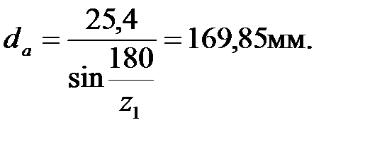
Sprocket lug circle diameter
Sprocket wheel circle diameter
 ,
,
Where r=0,5025d 1 –0.05 – radius of depressions;
d 1 – chain roller diameter (Table 17) d 1 =15,88.
Groove diameter  ,h=24.2 – width of chain plates,
  mm.
mm.
Table 17
Circuit parameters
| Circuit designation | t, mm | d 1 , mm | IN inn, mm | A, mm | h, mm |
| 2PR-12.7-3180 | 12,7 | 8,51 | 7,75 | 13,92 | 11,8 |
| 2PR-15,875-4540 | 15,875 | 10,16 | 9,65 | 16,92 | 14,8 |
| 2PR-25.4-11340 | 25,4 | 15,88 | 15,88 | 29,29 | 24,2 |
| 2PR-19.05-8120 | 19,05 | 11,91 | 12,7 | 25,5 | 18,2 |
| 2PR-31.75-17700 | 31,75 | 19,05 | 19,05 | 38,15 |
Note. in the designation of a chain, the number 2 indicates a double-row chain; for a single-row chain, the value A means the distance between the rows of chain rollers is 0.
Sprocket tooth width mm.
Sprocket crown width for double-row chain mm.
Rim thickness mm.
Release diameter to lighten the sprocket mm.
Disc thickness mm.
Construction of the sprocket tooth profile (Fig. 53).
Coordinate of the radius of curvature mm.
Tooth radius in longitudinal section mm.
Tooth width mm.

Rice. 53. Sprocket parameters:
a) front view; b) side view
Calculation of V-belt pulley parameters
Belt drives refer to gears with a flexible connection through which it is possible to provide stepless control of the gear ratio (variator Appendix 15). An example of a drawing of a pulley for a V-belt drive is given in Appendix 8.
The calculation of the parameters of the V-belt pulley is determined by the section of the belt GOST 1284-68.
For belt section 0, the calculated diameter of the drive pulley d 1 is determined from the standard series: 63, 71, 80, 90, 100, 112, 125, 140, 160, 180, 200, 224, 250. Pulley outer diameter = 125 mm.
Depending on the belt section (Table 18)
 = 125+2×2.5=130mm,
Select according to the table. 19.
Table 18
Main dimensions of V-belts
 |
|||||||||
| Type | Designation | Section dimensions | A, mm 2 | L, m | d 1min, mm | T 1 , N×m | |||
| b | b etc | h | y 0 | ||||||
| Normal section | ABOUT | 8,5 | 2,1 | 0,4...2,5 | £30 | ||||
| A | 2,8 | 0,56...4,0 | 15...60 | ||||||
| B | 10,5 | 0,8...6,3 | 50...150 | ||||||
| IN | 13,5 | 4,8 | 1,8...10 | 120...600 | |||||
| G | 6,9 | 3,15...15 | 450...2400 | ||||||
| D | 23,5 | 8,3 | 4,5...18 | 1600...6000 | |||||
| E | 6,3...18 | ³4000 | |||||||
| Narrow | UO | 8,5 | 2,0 | 0,63…3,55 | £150 | ||||
| UA | 2,8 | 0,8…4,5 | 90…140 | ||||||
| UB | 3,5 | 1,25…8,0 | 300…2000 | ||||||
| UV | 4,8 | 2,0…8,0 | ³1500 |
Table 19
Belt cross-section parameters and pulley groove dimensions
| Belt section | W p | b min | h min | e | f | r | d p for groove angle a | |||
| 34º | 36º | 38º | 40º | |||||||
| ABOUT | 8,5 | 2,5 | 7,0 | 12,0 | 8,0 | 0,5 | 50…71 | 80…100 | 112…160 | ³180 |
| A | 3,3 | 8,7 | 15,0 | 10,0 | 1,0 | 75…112 | 125…160 | 180…400 | ³450 | |
| B | 4,2 | 10,8 | 19,0 | 12,5 | 1,0 | 125…160 | 180…224 | 250…500 | ³560 | |
| IN | 5,7 | 14,3 | 25,5 | 17,0 | 1,5 | – | 200…315 | 355…630 | ³710 | |
| G | 8,1 | 19,9 | 37,0 | 24,0 | 2,0 | – | 315…450 | 500…900 | ³1000 | |
| D | 9,6 | 23,4 | 44,5 | 29,0 | 2,0 | – | 500…560 | 630…1120 | ³1250 | |
| E | 12,5 | 30,5 | 58,0 | 38,0 | 2,5 | – | – | 800…1400 | ³1600 |
Inner diameter mm, accept d h =110 mm.
Pulley rim width:
Where z– number of belts (grooves);
e– pitch between grooves;
f– distance from the edge of the rim.
Options e,f shown in Fig. 54.
Rim thickness for V-belts.
Sample diameter mm.
Hub length mm, d– diameter of the pulley hub hole.

Rice. 54. Pulley groove profile
Bibliography
1. Enterprise standard. Course and diploma design. General requirements for design: tutorial/ T.I. Parubochaya, N.V. Syreyshchikova, V.I. Guzeev, L.V. Vinokurova. – 4th ed., revised. and additional – Chelyabinsk: SUSU Publishing House, 2008. – 56 p.
2. Modern mechanical engineering. Machine parts and design fundamentals: textbook / P.N. Uchaev, S.G. Emelyanov, E.V. Pavlov et al. – M.: Academy, 2008. – 352 p.
3. Anuriev, V.I. Handbook of mechanical engineering designer: in 3 volumes / V.I. Anuriev /ed. I.N. Tough. –8th ed., revised. and additional – M.: Mechanical Engineering, 2001. – T.1. –920s.;T.2. – 912 s.; T.3. –864s.
4. Lelikov, O.P. Fundamentals of calculation and design of machine parts and components: lecture notes for the course “Machine Parts” / O.P. Lelikov. – 2nd ed., revised. and additional – M.: Mashinostroenie, 2004. – 440 p.
5. Dunaev, P.F. Design of units and parts of machines: a textbook for mechanical engineering specialties of universities / P.F. Dunaev, O.P. Lelikov. – M.: Academy, 2004. – 496 p.
6. Sheinblit, A.E. Course design of machine parts: textbook / A.E. Sheinblit. – Kaliningrad: Higher School, 2002. – 455 p.
7. Akhlyustina, V.V. Machine parts. Calculation mechanical gears. Design of chain drives: textbook / V.V.Akhlyustina, E.R. Logunova. – Chelyabinsk: YuUrGU Publishing House, 2008. – 135 p.
8. Ustinovsky, E.P. Multivariate design of cylindrical, conical and gear teeth worm gears using a computer: a textbook for course design / E.P. Ustinovsky, Yu.A. Shevtsov, Yu.K. Yashkov. – Chelyabinsk: ChSTU, 1995. – 105 p.
9. Sokhrin, P.P. Technical documentation in course design on machine parts: guidelines. P.P. Sokhrin, E.P. Ustinovsky, Yu.A. Shevtsov / ed. P.P. Sokhrina. – Chelyabinsk: ChSTU, 1994. – 73 p.
10. Akhlyustina, V.V. Metrology, standardization and certification: textbook / V.V. Akhlyustina, E.R. Logunova. – Chelyabinsk: SUSU Publishing House, 2008. – 211 p.
Applications
Annex 1
Appendix 3
Appendix 5
Appendix 7

Appendix 8


1. Alignment tolerance of plain bearings pos. 6, 8, 0.04 mm.
2. Parallelism tolerance of guides pos. 3, 0.05 mm.
3. Adjust the position of the slide, pos. 1, using screw pos. 7.
4. Sliding bearings pos. 6.8 and rolling bearings pos. 9, lubricate CIATIM 201 GOST 6267-74.
Appendix 11
Pusher for butt welding machine

Sprocket ring gear dimensions(according to GOST 591-69) for roller and bushing chains are presented in Fig. 7 and 8.
Note: The following dimensions are required to produce drawings of chain sprockets. To complete the assembly drawing of the drive, it is enough to calculate the pitch diameter, the diameter of the circle of the protrusions  and sizes shown in Fig. 8.
Initial data: chain pitch t, number of sprocket teeth z, diameter of the engagement element d 1 (according to table 1 of the appendix)
Pitch diameter  .
.
Diameter of the lugs circle.
Radius of depressions.
Diameter of the circle of the depressions  .
.
Blend radius.
Tooth head radius.
Half angle of depression  .
.
Mating angle  .
.
Half tooth angle  .
.
Displacement of the centers of the arcs of the depressions  .
.
Note: If the chain sprocket is made without shifting the centers of the arcs of the depressions, then  .
.
Straight profile section.
Distance from the center of the cavity arc to the center of the tooth projection arc  .
.
Point coordinates  :
: ;
; .
.
Point coordinates  :
: ;
; .
.
Minimum radius of tooth curvature  .
.
Distance from the top of the tooth to the center line of the rounding arcs  .
.
Groove diameter.
Curvature radius  = 1.6 mm at chain pitch
  up to 35 mm;
= 2.5 mm at chain pitch over 35 mm.
Tooth width for single row chain.
Tooth width for two- and three-row chain.
Crown width for two- and three-row chain  .
.
Protrusion circle diameter  calculated with an accuracy of 0.1 mm; other linear dimensions are up to 0.01 mm, and angular dimensions are up to 1.
3.2 Design of the hub and disk of chain sprockets
The design of the hub and disk of chain drive sprockets is shown in Fig. 9.
|
|
|
Rice. 9. Chain sprocket design. |
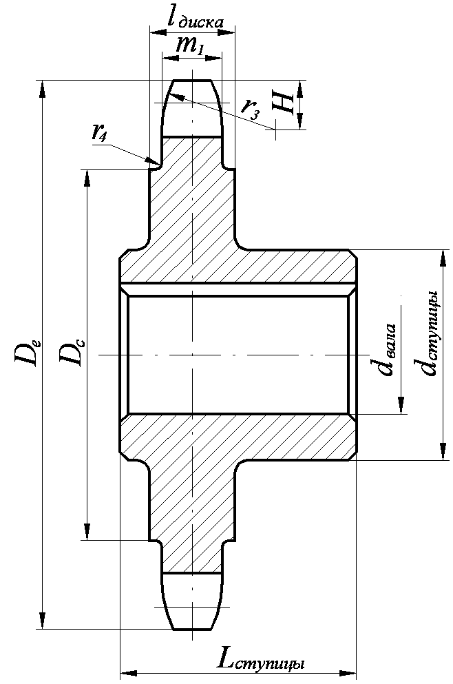
The value of the shaft diameter is taken from the design of the mechanisms that are connected by a chain transmission.
The hub diameter is usually taken:
 – for hubs made of cast iron;
 – for steel hubs.
The length of the hub is approximately equal to , it is finally accepted taking into account the results of calculating the keyed or splined connection.
At the stars large diameters the disc has increased thickness for increased rigidity. Disc width  . Small diameter sprockets do not need this. Their rim width is
  .
.
Calculated values  ,
, ,
, And
And  rounded to a value from a range of standard numbers ( - downward, the rest - up).
Maximum deviations and tolerances for some sprocket sizes are given in Table 2 of the Appendix.
3.3 Chain sprocket materials
The main materials for chain sprockets are medium-carbon and alloy steels 45, 40Х, 50Г2, 35ХГСА, 40ХН with surface or general hardening to a hardness of 45...55 HRC, or case-hardened steels 15, 20Х, 12ХН3А with carburization of 1...1.5 mm and hardening up to 55…60 HRC.
If you need silent and smooth operation of gears  5 kW and
  8 m/s, sprocket crowns can be made from plastics - textolite, polyformaldehyde, polyamides, which leads to reduced noise and increased durability of chains (due to reduced dynamic loads).
Sprockets of low-speed gears (up to 2 m/s) with a large number of teeth and a pitch of up to 25.4 mm in the absence of shock loads can be made from cast iron no lower than grade SCh 18-36 with subsequent heat treatment (ring hardness HB 363…429). In unfavorable conditions in terms of wear, for example, agricultural machines, anti-friction and high-strength cast iron with hardening is used.
Design calculation
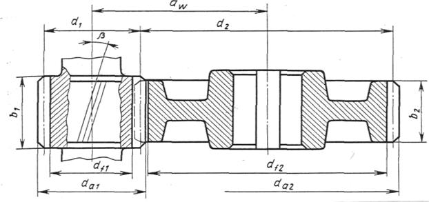
Fig.6. Geometric and power parameters of chain transmission
1. Determine the chain pitch p, mm
 ,
,
where a) T 1 - torque on the drive sprocket (on the low-speed gearbox shaft), N×m;
b) K e - operating coefficient, which is the product of five correction factors taking into account various conditions transmission work (Table 6)
K E =K D ×K C ×K q ×K reg ×K r;
c) Z 1 - number of teeth of the drive sprocket
where u is the gear ratio of the chain drive (u =i c). Round the resulting value Z l to an odd whole number, which in combination with an odd number of teeth of the driven sprocket Z 2 (see paragraph 2) and an even number of chain links l p(see point 5) will ensure more uniform wear of teeth and hinges;
d) [P c] - permissible pressure in the chain joints, N/mm 2, depends on the rotation speed of the drive sprocket n 1, rpm (rotation speed of the low-speed gearbox shaft), the expected chain pitch p;
e) n is the number of rows of the chain. For single-row PR type chains n= I.
Round the resulting value of the step p to the nearest standard value according to the table. 5P.
2. Determine the number of teeth of the driven sprocket
Round the resulting value Z 2 to an odd whole number. To prevent the chain from jumping:
Correction factor values TO. Table 6
| Transmission operating conditions | Coefficient | |||
| designation | meaning | |||
| Load dynamics | K D | 1,2…1,5 | ||
| K reg | 0,8 1,25 | |||
| Load dynamics | Uniform Variable or jerky | K D | 1,2…1,5 | |
| Adjusting the center distance | Moving supports Press sprockets Non-adjustable gears | K reg | 0,8 1,25 | |
| Gear position | Inclination of the line of star centers to the horizon, degrees | q=0…40 q=40…90 | K V | 1,15 1,05 |
| q£60 q>60 | K q | 1,25 | ||
| Lubrication method | Continuous (in an oil bath or from a pump) Drip Intermittent | K s | 0,8 1,5 | |
| Operating mode | Single shift Double shift Three shift | K r | 1,25 1,5 |
Permissible pressure in roller chain joints [ R c], N/mm 2. Table 7
3. Determine the actual gear ratio u f and check its deviation Du. from the given
;  .
.
4. Determine the optimal center distance a, mm.
From the condition of chain durability a = (30 ... 50) r. Then
 - center distance in steps.
5. Determine the number of chain links l r

Received value l p round to the nearest even number.
6. Specify the interaxal distance a р in steps
The obtained values a p ,a (see paragraph 7), l(see point 8) do not round to a whole number.
7. Determine the actual center distance a, mm
![]()
To ensure the possibility of eliminating chain slack, take the installation center distance
![]()
8. Determine the chain length l, mm
9. Determine the diameter of the sprockets, mm. Pitch circle diameter:
 - drive sprocket;
 - driven sprocket.
Protrusion circle diameter:
 - drive sprocket;
 - driven sprocket,
where K = 0.7 - tooth height coefficient;
 ;
;  - coefficients of the number of teeth of the drive and driven sprockets, respectively; - geometric characteristics of engagement (see Table 5P).
Diameter of the circle of the depressions:
Leading star;
Driven sprocket.
Verification calculation
10. Check the rotation speed of the smaller sprocket n 1, rpm
where n 1 is the rotation speed of the low-speed gearbox shaft;
 - permissible rotation speed.
11. Check the number of impacts of the chain on the sprocket teeth U, s -1
 - estimated number of chain strikes;
Permissible number of hits.
12. Determine the actual chain speed v, m/s
 .
.
13. Determine the circumferential force transmitted by the chain F t , H
 ,
,
where P 1 is the power on the drive sprocket, kW.
14. Check the pressure in the joints of the chain Р Ц, N/mm 2:
The suitability of the calculated circuit is determined by the relation.
Overloading the circuit is not allowed. In such cases, you can take a type IIP chain with a large pitch P and repeat checking the pressure P T in the hinges, or increase the number of teeth Z 1 of the chain being calculated and repeat the transmission calculation.
15. Check the strength of the chain. The strength of the chain is checked by the relation , where are the permissible and calculated safety factors for roller chains, respectively

where F p is the breaking load of the chain, N (Table 5P); F t - circumferential force transmitted by the chain, N; K d - coefficient taking into account the nature of the load (see clause 1); F o - chain pre-tension, N
![]() ,
,
where K f is the sagging coefficient; K f = 6 for horizontal gears;
K f = 3 - for gears inclined to the horizon up to 40°;
K f = 1 - for vertical gears; q - mass of 1 m of chain, kg/m;
a - center distance, m; g =9.81 m/s 2 - acceleration free fall;
F v - chain tension due to centrifugal forces, N:
![]() ,
,
where v is the actual speed of the chain (see paragraph 12).
Allowable safety factor [S]
for roller (bushing) chains at Z 1 = 15...30.
Table 8
| Step R, mm | Rotation speed of the smaller sprocket n 1, rpm | ||||||||
| 12,7 | 7,1 | 7,3 | 7,6 | 7,9 | 8,2 | 8,5 | 8,8 | 9,4 | |
| 15,875 | 7,2 | 7,4 | 7,8 | 8,2 | 8,6 | 8,9 | 9,3 | 10,1 | 10,8 |
| 19,05 | 7,2 | 7,8 | 8,4 | 8,9 | 9,4 | 9,7 | 10,8 | 11,7 | |
| 25,4 | 7,3 | 7,6 | 8,3 | 8,9 | 9,5 | 10,2 | 10,8 | 13,3 | |
| 31,75 | 7,4 | 7,8 | 8,6 | 9,4 | 10,2 | 11,8 | 13,4 | - | |
| 38,1 | 7,5 | 8,9 | 9,8 | 10,8 | 11,8 | 12,7 | - | - | |
| 44,45 | 7,6 | 8,1 | 9,2 | 10,3 | 11,4 | 12,5 | - | - | - |
| 50,8 | 7,7 | 8,3 | 9,5 | 10,8 | - | - | - | - |
16. Determine the pressure force of the chain on the shaft F on , N:
![]() ,
,
where K B is the shaft load factor (see Table 8).
For shock loads, increase the K B value by 10...15%.
The drive sprocket of the chain drive is located on the low-speed gearbox shaft. Initial data for calculation:
P = 6.92 kW; n = 301.21 min -1
T = 219.47 N m i C = u = 3
ω=31.53s -1
Solution
1. Determine the chain pitch using the formula:
We accept standard value chain pitch (with a margin) according to table. 5P,
P = 38.1 mm, Where T 1 = 219.47 N m
the values of the coefficients are determined from the table. 6;
K D = 1.2; K C = 1.5(with periodic lubrication method); K θ = 1.0(with horizontal transmission); K REG = 1.25(with unregulated transmission); K P = 1.25(with a two-shift transmission mode); Z 1 – number of small sprocket teeth
We accept Z 1 = 23
– permissible pressure in the chain joints at n 1 = 301.21 min -1, And
p = 38.1 mm. [R C] = 26 N/mm 2(Table 7); v=1(with a single-row chain).
2. Determine the number of teeth of the driven sprocket
We accept Z2 = 69; Z 2
3. Determine the actual gear ratio

4. Determine the optimal center distance from the condition of chain durability
We accept a = 1500 mm, then the center distance in steps

5. Determine the number of chain links
We accept l P = 126
6. We specify the center distance a P in steps:
7. Determine the actual center distance
We accept the final center distance taking into account the elimination of chain slack from its own weight
8. Determine the length of the chain
9. Determine the diameters of the sprockets:
pitch circle


lug circumference


d 1 = 11.1 mm– table 5P
depression circumference
Verification calculation
10. Check the rotation speed of the smaller sprocket according to the conditions
n 1 ≤
Permissible rotation speed

n 1 =301.21 min -1< =398мин -1
the condition is met.
11. Check the number of impacts of the chain on the sprocket teeth according to the condition
U ≤ [U]
Estimated number of chain strikes

Permissible number of strokes

U=3.67< [U]=13,3
the condition is met.
12. Actual chain speed
13. Circumferential force transmitted by the chain

14. Check the pressure in the chain joints according to the conditions
![]()
Projection area of the hinge support surface
b 3 = 25.4 mm 2– table 5P
![]()
= 26 N/mm 2– table 7
P C = 15.67 N/mm 2< = 26 Н/мм 2 .
The calculated circuit is suitable for operation.
15. Check the strength of the chain by the ratio
S ≥ [S]
Chain pre-tension
K f = 6.0– for horizontal chains – takes into account sagging;
q = 5.5 kg/m– mass of 1 m of chain (Table 5P);
g = 9.81 m/s 2 ;
K D = 1.2(see point 1).
Chain tension from centrifugal force, N
F P = 12700 daN = 127 kN– breaking load of the chain, table. 5P.
Allowable safety factor for roller chains according to table. 8. [S] = 9.8
S = 51.3 > [S] = 9.8
The strength condition is met.
16. Determine the pressure force of the chain on the shaft
K B = 1.15 – Table 6.
Gear calculation
Before you start calculating gears, it is necessary to study the main criteria for their performance /1/ p 126...128.
When transmitting torque (Fig. 7, a) in engagement, in addition to the normal force F n, there is a friction force F tr = F n ∙f associated with sliding. Under the influence of these forces, the tooth is in a complex stressed state (Fig. 7, b).

Two main stresses have a decisive influence on its performance: contact stress σ H and bending stress σ F. For each tooth, these stresses change over time in an intermittent zero cycle (see Fig. 7, a). The time of stress for one revolution of the wheel (t 1) is equal to the duration of engagement of one tooth (t 2).
Variable stresses are the cause of fatigue failure of teeth: tooth breakage from bending stresses (Fig. 8, a), chipping of the tooth surface from contact stresses (Fig. 8, b), wear is also associated with contact stresses and friction in engagement (Fig. 8, c), seizing and other damage to the tooth surface.

Rice. 8. Types of tooth damage
Calculation of contact strength is basic for closed (operating in conditions of abundant lubrication) gears. The purpose of the calculation is to prevent fatigue chipping of the working surfaces of the teeth over a given service life. Bending calculation is fundamental for teeth open gears with high surface hardness. The purpose of bending calculations is to prevent tooth breakage.
Pay attention to the determination of the forces acting in gears and which are the starting point for calculating teeth, shafts and selecting bearings. It should be remembered that gear calculations are performed based on calculated loads. These loads are greater than the nominal (theoretical) ones, since due to the deformation of wheels, shafts, supports, body parts and inevitable errors in their manufacture and installation, additional dynamic loads arise. Design load
where T, F t - rated load (torque on the shaft and circumferential force); K - design load coefficient
K β - load concentration coefficient, depends mainly on the asymmetry of the location of the wheels relative to the supports and the relative width of the wheel Ψ bd= , which affect the deformation of parts and tooth misalignment; K υ - dynamic load coefficient, depends mainly on the peripheral speed and manufacturing accuracy gear wheels; K β ,K υ are selected from tables and graphs.
For design calculations, approximately K = 1.1... 1.5 is taken. A lower value is taken for running-in materials (HB≤ 350) with a symmetrical arrangement of wheels for indirect teeth.
Understand that right choice The material for the gears determines the dimensions and cost of the transmission. Steel is currently the main material for the manufacture of gears. If there are no special requirements regarding the dimensions of the gear, you should choose materials with average mechanical characteristics, with a hardness ≤ 350HB (heat treatment normalization or improvement). This ensures clean cutting of teeth after heat treatment, high accuracy manufacturing and good wearability of teeth.
For uniform wear of the teeth and better running-in, the hardness of the HB 1 gear is assigned greater than the hardness of the HB 2 wheel by (20 ... 50) HB.
Choice of material, heat treatment and hardness. Table 9
| Parameter | For gears with straight and indirect teeth at low (P≤2 kW) and medium (P≤10 kW) power; HB 1sr -HB 2sr =20...50 | For gears with indirect teeth at average (P≤10 kW) power; NV 1 sr -NV 2 sr ≥70 | |||
| Gear, worm | Wheel | Gear, worm | Wheel | ||
| Material | Steel 35, 40, 45, 40Х, 40ХН, 35ХМ | Steel 40Х, 40ХН, 35ХМ | |||
| Heat treatment | Improvement Normalization | Improvement + +High-frequency hardening | Improvement | ||
| Hardness | ≤350NV | ≥45 HRC e | ≤350 HB | ||
| Allowable voltage for the number of voltage cycles N HO ; NFO , N/mm 2 | [σ] Ho | 1.8NV av +67 | 14HRC esr + +170 | 1.8 HB avg + +67 | |
| [σ] Fo | 1.03 NV avg | at m ≥ 3 mm | 1.03 NV avg | ||
| at m < 3 mm | |||||
Notes: l. In gear transmissions, the steel grades of the gears and wheels should be the same. At the same time, for gears whose dimensions do not require high requirements, cheap steel grades of type 40, 40X should be used. 2. For open gear wheels large diameter(D≥500 mm) use steel casting (35L, 40L, 45L, 40GL, heat treatment - normalization, improvement) paired with a forged gear made of steel of the appropriate grade.
Allowed contact stresses when calculating contact strength, they are determined separately for gear teeth [σ] H 1 and wheel teeth [σ] H 2 .
Mechanical characteristics of steels. Table 10

| steel grade | D before, mm | S before, mm | Heat treatment | Workpiece hardness | σ in | σ t | σ -1 |
| Surface and core | N/mm 2 | ||||||
| Any | Any | N | 163...192 НВ | ||||
| U | 192...228 НВ | ||||||
| Any | Any | N | 179...207 НВ | ||||
| U | 235...262 NV | ||||||
| U | 269...302 НВ | ||||||
| 40X | U | 235...262 NV | |||||
| 40X | U | 269...302 НВ | |||||
| 40X | U+HDTV | 269...302 НВ | |||||
| 40ХН | U | 235...262 NV | |||||
| 40ХН | U | 269...302 НВ | 920" | ||||
| 40ХН | U+HDTV | 269...302 НВ | |||||
| 35ХМ | U | 235...262 NV | |||||
| 35ХМ | U | 269...302 НВ | |||||
| 35ХМ | U+HDTV | 269...302 НВ | |||||
| 35 L | Any | Any | H | 163...207 НВ | |||
| 40L | » | » | H | 147 NV | |||
| 45L | U | 207...235 НВ | |||||
| 40GL | U | 235...262 NV |
Notes: 1. In the “Heat treatment” column the following designations are accepted: H-normalization, U-improvement, high-frequency hardening with high-frequency currents. 2. For cylindrical and bevel wheels, use the smaller values of C zag, S zag.
[σ] H 1 =K HL 1 [σ] HO 1 ; [σ] H 2 =K HL 2 [σ] HO 2
where [σ] H 01, [σ] H 02 is the permissible contact stress corresponding to the contact endurance limit with the number of stress cycles N HO (Table 11); K HL - durability coefficient
KHL = ,
where N is the number of voltage cycles over the entire service life
N=573ω ∙L h ,
where ω - angular velocity corresponding shaft, sec -1; L h – drive service life, hour.
The definition of K HL taking into account the drive load schedule is given in the literature /2/ from 15...16.
For normalized and improved wheels 1.0≤ K HL ≤2.6.
If N > N HO, then take K HL = 1.
The value of the number of N HO cycles. Table 11
Cylindrical and bevel gears with straight and indirect teeth at НB 1ср -НB 2ср = 20 ... 50 are calculated based on the lower value of [σ] H, i.e. along the less durable teeth of the gear pair.
Gear drives with indirect teeth with HB 1ср -HB 2ср ≥70 and wheel tooth hardness ≤ 350 НB are calculated based on the average permissible contact stress
[σ] H =0.45([σ] H 1 + [σ] H 2),
in this case, [σ] H should not exceed 1.23 [σ] H 2.
The permissible stresses when calculating bending are determined for the gear and wheel separately
[σ] F 1 =K FL 1 [σ] F 01 ; [σ] F 2 =K FL 2 [σ] F 02 ,
where [σ] F 0 is the permissible bending stress corresponding to the bending endurance limit with the number of cycles of stress changes N fo (Table 9); K fl - durability coefficient
KFL= ,
where N F 0 is the number of cycles of voltage changes corresponding to the endurance limit. For all steels N fo = 4∙10 6. With hardness НB≤ 350.
1 ≤ K FL ≤ 2.08 .
If N>N F 0, take K fl =1.
When designing a spur gear, follow the sequence below:
1. Select the material for the gear transmission and determine the permissible stresses for calculating contact endurance and bending.
2. Determine the center-to-axle transmission distance a w, mm
a w =K a (u+1)  ,
,
where K a =43 for helical and chevron gears;
K a =49.5 for straight teeth;
Ψa= - wheel crown width coefficient;
Ψ a is taken from a number of standard numbers: 0.1; 0.15; 0.2; 0.25; 0.315; 0.4; 0.5; 0.63 depending on the position of the wheels relative to the supports: with a symmetrical arrangement 0.4…0.5; with asymmetrical 0.25...0.4; with console 0.2…0.25.
u - gear ratio; T 2 - rotating torque on the low-speed gearbox shaft, H∙m; [σ] H - permissible contact stress; K n b - load concentration factor. For running-in teeth at constant load K H b = 1.
The resulting value of the interaxial distance a w should be rounded to the nearest value from a number of normal linear dimensions (Table 1P).
3. Determine the engagement module m, mm
m ≥ 
where K m = 6.8 - for spur gears; K m = 5.8 – for helical and chevron teeth;
d 2 = pitch diameter wheels, mm; b 2 = Ψ a ∙a w - wheel crown width, mm;
[σ] F - permissible bending stress of the wheel material with a less strong tooth, N/mm 2.
Determine the engagement modulus from the condition m = (0.01...0.02) and select its value from the standard series of numbers (no less than previously calculated).
m, mm 1st row -1.0; 1.5; 2; 2.5; 3; 4; 5; 6; 8; 10
2nd row -I,25; I,75; 2.25; 2.75; 3.5; 4.5; 5.5; 7; 9
When choosing a module, row 1 is preferable. In power gears at HB≤ 350, take m > 1 mm.
4. Determine the angle of inclination of the teeth β min for helical and herringbone gears
β min =arcsin.
IN helical gears take β = 8° ... 20°; in chevron - β= 25° ... 40°.
5. Determine the total number of gear and wheel teeth for spur wheels Z ∑ = Z 1 +Z 2 = ; for helical and chevron teeth Z ∑ = Z 1 +Z 2 = ![]() .
.
Round the resulting value Z ∑ to the nearest whole number.
6. Clarify the actual value of the tooth angle
Accuracy of angle β calculation to the fifth decimal place
7. Determine the number of gear teeth
Round the value of Z 1 to the nearest whole number. To reduce noise and avoid cutting teeth, it is recommended: Z 1 ≥17.
When receiving Z 1 ≤17, take Z 1 =17, or design cutting teeth with a positive tool offset. The methodology for calculating such gearing can be found in the literature: /2/ c 21...22.
8. Determine the number of wheel teeth
Z 2 = Z ∑ -Z 1 .
9. Determine the actual gear ratio u f and check its deviation Δu from the given u: u f = ;
Δu= ![]() ≤ 4% .
≤ 4% .
10. Determine the actual center distance:
a w = - for spur gears;
a w =  - for helical gears.
11. Determine the main geometric parameters of the transmission using the formulas given in table. 12.
Rice. 9. Geometric parameters cylindrical gear transmission.
The accuracy of calculating wheel diameters is up to 0.01 mm. The value of the width of the gear rims is rounded to a whole number according to normal linear dimensions(Table 1 P).
Geometric parameters of gears. Table 12
Verification calculation
12. Check the center distance:
13. Check the suitability of the wheel blanks (see Table 10).
14. Check contact stresses σ H, N/mm 2:
σ H =K 
where K = 436 - for spur gears; K= 376 - for helical and chevron wheels.
F t = - circumferential force in engagement, N;
K N a - coefficient taking into account the distribution of load between the teeth; K H a = 1 - for spur wheels; for helical wheels K N a is determined according to the graph in Fig. 10 depending on the peripheral speed of the wheels v = , m/s and the degree of transmission accuracy (Table 13); K Hυ - dynamic load coefficient (Table 14).

Rice. 10 Graph for determining the coefficient K H a from accuracy curves
Transmission underload is allowed (σ H<[σ] H) не более 15 %, перегрузка (σ H >[σ] H) up to 5%. If the condition is not met, you should increase the center distance a w , the width of the wheels, or assign other wheel materials or other heat treatment, recalculate the allowable stresses and repeat the entire transmission calculation.
15. Check the bending stresses of the gear teeth σ F 1 and the wheel σ F 2, N/mm 2: σ F 2 =Y F 2 ∙Y β ∙ ∙K F a ∙K Fβ ∙K Fυ ≤[σ] F 2 ;
σ F 1 =σ F 2 ∙ ≤[σ] F 1 ,
where m is the engagement module, mm; b 2 - width of the wheel ring gear, mm; F t - circumferential force in engagement, N; K F a =1 for spur gears. For helical and chevron teeth, depending on the degree of accuracy:
The values of the coefficients K Hυ and K Fυ for HB 2 ≤350. Table 14
| Degree of accuracy | Coefficient | Peripheral speed v , m/s | |||||
| K Hυ K F υ | 1,03 1,01 1,06 1,02 | 1,06 1,02 1,13 1,05 | 1,12 1,03 1,26 1,10 | 1,17 1,04 1,40 1,15 | 1,23 1,06 1,58 1,20 | 1,28 1,07 1,67 1,25 | |
| K Hυ K F υ | 1,04 1,02 1,08 1,03 | 1,07 1,03 1,16 1,06 | 1,14 1,05 1,33 1,11 | 1,21 1,06 1,50 1,16 | 1,29 1,07 1,67 1,22 | 1,36 1,08 1,80 1,27 | |
| K Hυ K F υ | 1,04 1,01 1,10 1,03 | 1,08 1,02 1,20 1,06 | 1,16 1,04 1,38 1,11 | 1,24 1,06 1,58 1,17 | 1,32 1,07 1,78 1,23 | 1,4 1,08 1,96 1,29 | |
| K Hυ K F υ | 1,05 1,01 1,13 1,04 | 1,1 1,03 1,28 1,07 | 1,2 1,05 1,50 1,14 | 1,3 1,07 1,77 1,21 | 1,4 1,09 1,98 1,28 | 1,5 1,12 2,25 1,35 |
Note. The numerator shows data for straight teeth and the denominator for helical and circular gears.
K Fβ =1 - for running-in teeth; To Fυ - according to table 13; Y F 1 and Y F 2 are the tooth shape coefficients, determined from Table 15, depending on the number of teeth of the gear Z 1 and the wheel Z 2 - for spur gears. For helical wheels and chevron wheels - depending on the equivalent number of gear teeth Z υ 1 = and wheel Z υ 2 = ; Y β =1 - for spur gears; Y β =1- - for helical gears;
[σ] F 1 and [σ] F 2 - permissible stresses of the gear and wheel, N/mm 2.
Tooth shape coefficients Y F 1 and Y F 2. Table 15
| z or z υ | Y F | z υ | Y F | z υ | Y F | z υ | Y F | z υ | Y F | z υ | Y F |
| 4,28 | 3,92 | 3,80 | 3,66 | 3,61 | 3,62 | ||||||
| 4,27 | 3,90 | 3,78 | 3,65 | 3,61 | ∞ | 3,63 | |||||
| 4,07 | 3,88 | 3,75 | 3,62 | 3,60 | |||||||
| 3,98 | 3,81 | 3,70 | 3,62 | 3,60 |
Note. The tooth shape coefficients Y F correspond to the tool displacement coefficient x=0.
If during the verification calculation σ F is significantly less than [σ] F , then this is acceptable, since the load capacity of closed gears is limited by contact strength.
STATE STANDARD OF THE USSR UNION
UNIFIED SYSTEM OF DESIGN DOCUMENTATION
RULES FOR EXECUTION OF DRAWINGS OF VARIOUS PRODUCTS
RULES FOR EXECUTION OF WORKING DRAWINGS
DRIVE ROLLER SPROCKETS
AND BUSH CHAINS
GOST 2.408-68
MOSCOW - 1998
STATE STANDARD OF THE USSR UNION
|
Unified system of design documentation RULES FOR EXECUTION OF WORKING DRAWINGS Unified system for design documentation. |
Date of introduction 01.01.71
1. This standard establishes the rules for the execution of gearing elements on the working drawings of sprockets for drive roller and bushing chains with a tooth profile in accordance with GOST 591.2. Working drawings of drive roller and bushing chain sprockets must be made in accordance with the requirements of the standards of the Unified System of Design Documentation and this standard. 3. In the image of the sprocket (Fig. 1 - 3) indicate: the width of the sprocket tooth; the width of the crown (for a multi-row sprocket); the radius of curvature of the tooth (in the axial plane); the distance from the top of the tooth to the line of centers of the rounding arcs (in the axial plane); rim diameter (largest); radius of curvature at the rim boundary (if necessary); diameter of the protrusion circle; surface roughness of the tooth profile, end surfaces of the teeth, surface of the protrusions and roughness of the curvature surfaces of the teeth (in the axial plane). 4. On the star drawing, a table of parameters is placed in the upper right corner. The dimensions of the table columns, as well as the dimensions that determine the location of the table in the drawing field, are shown in Fig. 1 . 5. The table of parameters of the sprocket ring gear consists of three parts, which are separated from each other by solid main lines: the first part - basic data (for manufacturing); the second part - data for control; the third part - reference data (see Fig. 1 - 3). 6. In the first part of the table of parameters, the following is given: the number of sprocket teeth z; parameters of the mating chain: pitch t and diameter of the roller d 3 or bushing d 2; tooth profile according to GOST 591 with the inscription: “With offset” or “Without offset” (centers of the arcs of the depressions ); accuracy group according to GOST 591.7. In the second part of the table of parameters, the following are given: the size of the diameter of the circle of the depressions D i and maximum deviations (for sprockets with an even number of teeth) or the size of the largest chord L x and maximum deviations (for sprockets with an odd number of teeth); tolerance for pitch difference; radial runout tolerance circumference of the depressions; tolerance for the end runout of the ring gear.8. In the third part of the table of parameters, the following is given: the diameter of the pitch circle d d; the width of the internal plate of the chain h; the distance between the internal plates of the chain b 3; for a multi-row chain - the distance between the rows of the chain A; the number of rows of the chain. If necessary, indicate other reference data related to the engagement elements.6 - 8. (Changed edition, Amendment No. 2). 9. If the sprocket consists of several gear rings that differ in the number of teeth or in the number of teeth and chain pitch, then the parameter values are indicated in the table of parameters for each ring in separate columns. Each gear ring and the corresponding column (column) of the table are designated in capital letters Russian alphabet (see drawing 3).10. Unused columns of the parameter table are excluded or crossed out. 11. Examples of the implementation of engagement elements on working drawings of sprockets are shown in Fig. 13 .
An example of a sprocket ring gear for a single-row normal drive roller chain
*Size for reference.
An example of a drawing of sprocket teeth for a three-row drive roller chain

*Size for reference.
An example of a drawing of the ring gears of a sprocket block for single-row chains

*Size for reference.
(Changed edition, Amendment No. 2).
INFORMATION DATA
1. DEVELOPED AND INTRODUCED by the Committee on Standards, Measures and measuring instruments under the Council of Ministers of the USSRDEVELOPERS.R. Verchenko, Ya.G. Starozhilets, Yu.I. Stepanov, V.I. Dozortsev2. APPROVED AND ENTERED INTO EFFECT by the Resolution of the Committee of Standards, Measures and Measuring Instruments under the Council of Ministers of the USSR dated June 19, 1968 No. 948 Change No. 2 was adopted by the Interstate Council for Standardization, Metrology and Certification (Minutes No. 8 dated October 12, 1995) Registered by the Technical Secretariat of the IGU No. 1777 For acceptance changes voted:
|
State name |
Name of the national standardization body |
| Republic of Belarus | State Standard of Belarus |
| The Republic of Kazakhstan | Gosstandart of the Republic of Kazakhstan |
| The Republic of Moldova | Moldovastandard |
| Russian Federation | Gosstandart of Russia |
| The Republic of Tajikistan | Tajikgosstandart |
| Turkmenistan | home state inspection Turkmenistan |
| Ukraine | State Standard of Ukraine |
Sprocket for traction chains- This is a profiled wheel that has teeth on its outer surface designed to engage with a track, chain or other product that has notches or grooves.
Stars differ from both gears and pulleys. Their main difference from the latter is that they never engage directly with each other. As for the pulleys, they have smooth surfaces that engage the belts, while the sprockets have teeth.
Chain sprockets, these are wheels made of metal, and they are used to ensure reliable engagement of the rollers with which the drive chain is equipped. One of the main characteristics of sprockets is the number of teeth. In addition, they may have one or more rows, and depending on this, they are divided into single-row and multi-row.
Asterisks for traction chains are widely used in torque transmission systems used in agricultural and industrial equipment, tracked vehicles, various construction mechanisms and so on.
Besides them there are also stars tensioners, used to prevent severe sagging of chains. Most often they are installed on driven branches.
Asterisks for traction drive chains are part of chain transmissions and are one of their main elements. The drives themselves consist of two sprockets, one of which is the drive sprocket and the other is the driven sprocket, depending on which shaft they are located on.
Chain transmissions are very popular and widely used in a variety of machines and mechanisms due to the fact that they have a high load capacity, high efficiency, and are capable of transmitting significant power. In addition, these systems have a constant average gear ratio.
Depending on how accurately they are made stars, from what material they are made, how they are heat treated, what is the quality of the surface of the teeth, largely depends on the operation of the chain drive.
Star shape, as well as what exact design dimensions they have, depend on several factors. The main ones are the gear ratio that must be provided, as well as the parameters of the selected chain. It is this that decisively determines how many teeth the sprocket should have. As for the main characteristics and parameters of these parts, they are determined by the standard GOST 13576-81 .
By GOST 591-69 profiled stars designed for use in combination with bushing and roller chains. The teeth of such sprockets have working profiles, which are outlined by arcs corresponding to circles. Sprockets with teeth, the working profiles of which are straight, are used for toothed chains. Form cross section The profile of the star depends on how many rows it has.
The main requirements for the material from which they are made stars, are the ability to withstand shock loads and wear resistance. Most often, steel is used to produce sprockets. 45 , 40 , 40X and some others, and they are hardened to hardness HRC 40…50 . Case-hardened steel grades are also used 20X, 15 ,20 , which heats up to hardness HRC 50…60 . For the production of those sprockets that are used in low-speed gears, modified or gray cast iron grades are used SCH 20, SCH 15. Sprockets equipped with plastic toothed rims are also now used, which provide low level noise and reduced chain wear.
Asterisks for traction chains, they are mandatory elements of chain transmissions, which continue to be in great demand for use in various machines and mechanisms.